Resonant converter based on ON/OFF control

A technology of resonant converter and inverter circuit, which is applied in the direction of control/regulation system, output power conversion device, DC power input conversion to DC power output, etc. It can solve large circulating current, reduce converter efficiency, and reduce converter efficiency. Stability and other issues, to achieve the effect of wide voltage gain range, increase power density, and reduce the volume of magnetic components

Inactive Publication Date: 2020-06-09
HUBEI UNIV OF TECH
View PDF4 Cites 4 Cited by
  • Summary
  • Abstract
  • Description
  • Claims
  • Application Information

AI Technical Summary

Problems solved by technology

[0004] The LLC resonant converter controlled by pulse frequency is difficult to achieve a wide gain range due to the limitation of the switching frequency range, and it cannot better meet the application occasions with wide voltage requirements.
Also, pulse frequency modulation control increases the complexity of resonance parameter design
In particular, when the switching frequency of the resonant converter is much lower than the resonant frequency, there will be a large circulating current in the resonant circuit, which will generate additional conduction loss and switch turn-off loss, which will reduce the efficiency of the converter. The fundamental wave analysis method (FHA

Method used


Image

  • Resonant converter based on ON/OFF control
  • Resonant converter based on ON/OFF control
  • Resonant converter based on ON/OFF control

Examples


Embodiment Construction

[0033] The technical solution of the present invention will be described below in conjunction with the accompanying drawings and embodiments, so that those skilled in the art can better understand the present invention.

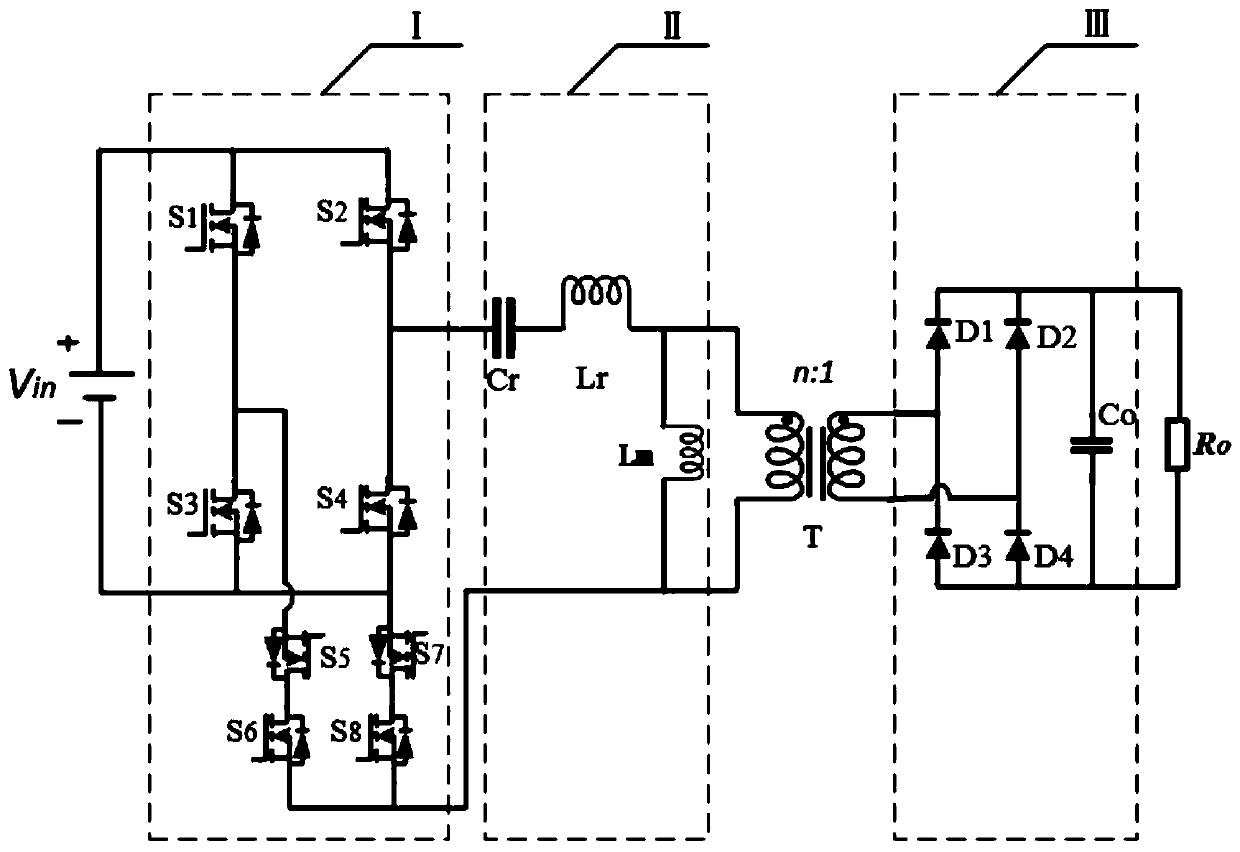
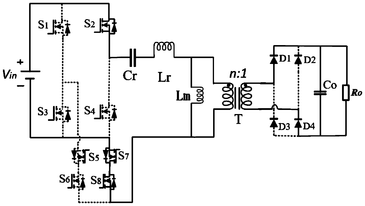
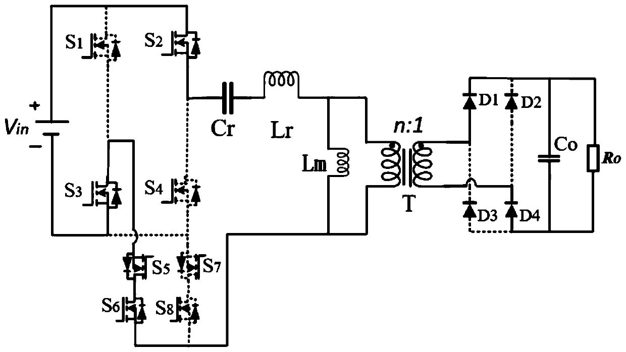
[0034] Two auxiliary bidirectional switches are added to the primary side square wave inverter circuit of the resonant converter of the present invention, and the bidirectional switch adopts ON / OFF control, so the resonant converter can work in the full-bridge LLC resonant converter mode or Works in half-bridge LLC resonant converter mode. Among them, "ON" means "conduction", and "OFF" means "turn off". Due to this resonant converter topology and its switching control mode, the switching frequency of the resonant converter has a narrow range, and the adjustment of the ultra-wide range voltage gain is realized. The primary side switching tube realizes zero voltage switching (ZVS), and the secondary side The rectifier diode achieves zero current switching (ZCS...


PUM


Abstract

The invention provides a resonant converter based on ON/OFF control. The resonant converter comprises a primary side square wave inversion circuit I, a primary side LLC resonance circuit II, a transformer T, a secondary side full-bridge rectification circuit III and an output resistance load Ro. The resonant converter is characterized in that two auxiliary two-way switches are added to the primaryside square wave inverter circuit I; ON/OFF control is adopted for the auxiliary two-way switches, so that the resonant converter can work in a full-bridge LLC resonant converter mode and can also work in a half-bridge LLC resonant converter mode. Due to the topological structure of the resonant converter and the switching type control mode of the resonant converter, the switching frequency change range of the resonant converter is narrow, ultra-wide-range voltage gain adjustment is achieved, zero-voltage switching of a primary side switching tube is achieved, zero-current switching of a secondary side rectifying diode is achieved, and switching loss is reduced.

Description

technical field [0001] The invention relates to the technical field of isolated DC-DC converters, in particular to a resonant converter with a new topology based on ON / OFF control. Background technique [0002] Isolated DC-DC converters are currently widely used, including data centers, server power supplies, electric vehicle on-board battery chargers, photovoltaic DC microgrids, fuel cells, LED drive circuits, etc. In many of the above applications, the converter needs Meet the wide voltage working requirements. [0003] Converters mainly include two types, the first is a full-bridge converter with pulse width modulation (PWM), and the other is a resonant converter with pulse frequency modulation (PFM). Due to the large circulating current, the narrow soft switching range of the lagging arm, the high voltage stress of the rectifier diode, and the reverse recovery of the diode, the phase-shifted full-bridge converter cannot achieve high efficiency. The difference is that t...

Claims


Application Information

Patent Timeline
IPC IPC(8): H02M3/335
CPCH02M3/33569H02M1/0058Y02B70/10
Inventor 潘健刘松林吕磊陈凤娇陈庆东石迪宋豪杰陈光义
Owner HUBEI UNIV OF TECH
Why Eureka
Try Eureka