Traveling truck

A technology of driving platform and trolley, which is applied in the direction of electric vehicles, vehicle parts, welding equipment, etc., can solve the problem of adjustment of difficult positions for operators, and achieve good welding results

Pending Publication Date: 2020-06-09
KOIKE SANSO KOGYO CO LTD
View PDF7 Cites 0 Cited by
  • Summary
  • Abstract
  • Description
  • Claims
  • Application Information

AI Technical Summary

Problems solved by technology

[0011] In particular, the object is to solve the following problem: when positioning relative to the position to start welding and the point of piercing

Method used


Image

  • Traveling truck
  • Traveling truck
  • Traveling truck

Examples


Example Embodiment

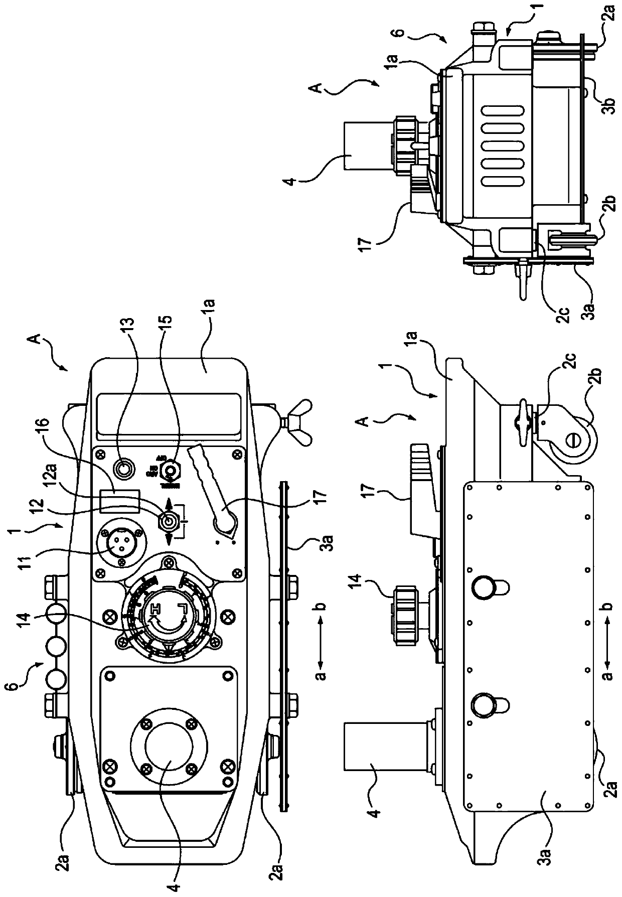
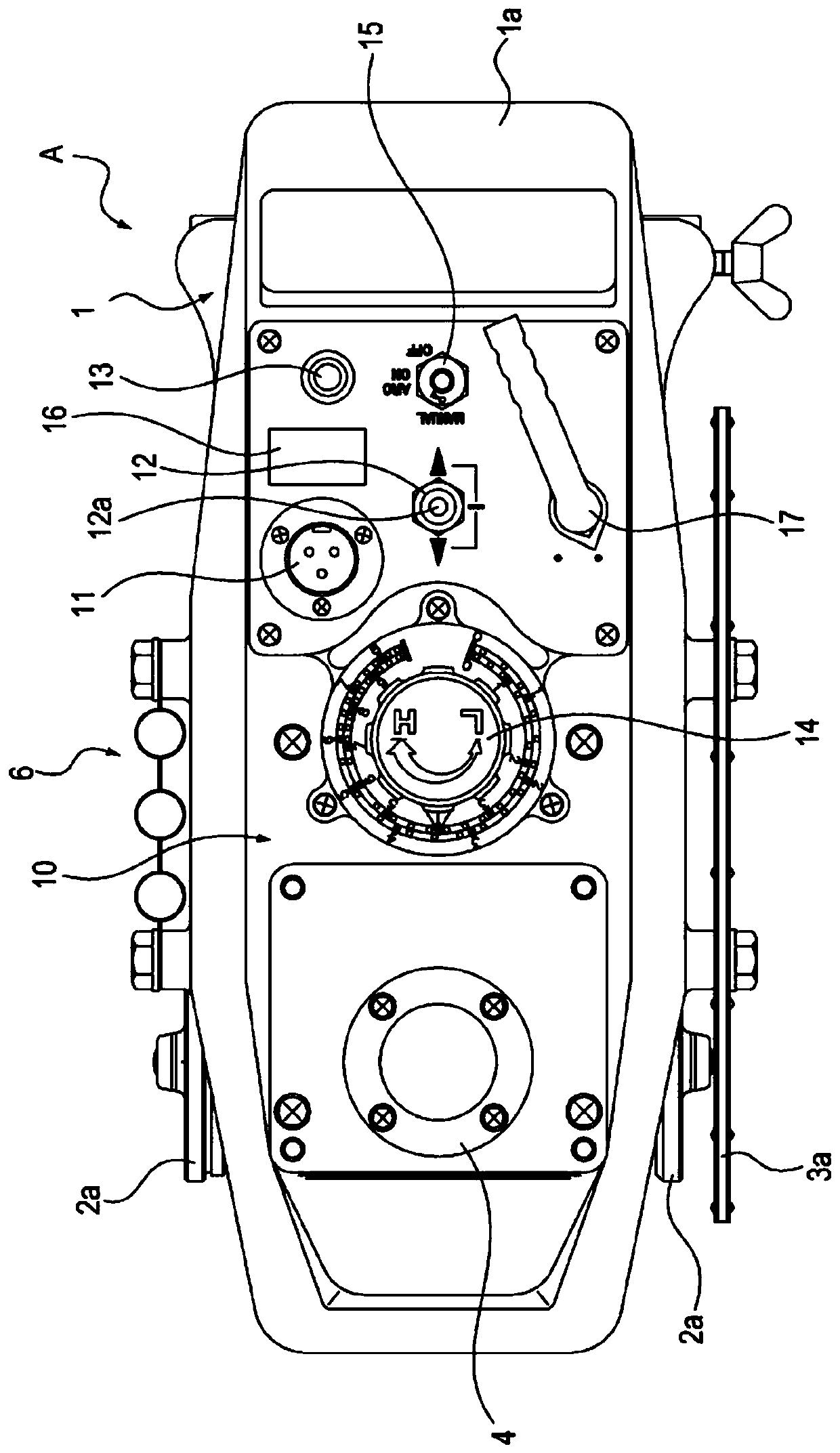
[0034] Hereinafter, the traveling vehicle of the present invention will be described. The present invention is a traveling cart that is equipped with a torch such as a cutting torch or a welding torch and is used when cutting or welding a to-be-processed material represented by a steel plate (hereinafter referred to as a "steel plate"). In particular, it is configured to reliably perform processing in the case of starting or ending cutting of the material to be processed from the end surface, processing in the case of piercing the material to be processed and then continuously cutting from the piercing point, or starting welding When processing, or when the welding is terminated.

[0035] As a torch mounted on a traveling cart and used for cutting steel plates, a torch for gas cutting, a torch for plasma cutting, and the like can be selectively used. In a gas cutting torch, it is connected to a fuel gas supply device and an oxygen supply device via a plurality of hoses. In a pla...


PUM


Abstract

A traveling truck can facilitate operations performed when starting and ending machining of a machined material. A traveling truck A has: a drive motor 25; a three-position selection switch 12; a press-button switch 13 for enabling travel at a preset secondary speed; a speed setting dial 14 for setting a machining speed or the secondary speed; and a control unit 20 that stores the machining speedand the secondary speed in accordance with the operation amount of the speed setting dial, controls the rotational direction and the rotational speed of the drive motor in response to a travel signalfrom the three-position selection switch, and controls the rotational speed corresponding to the secondary speed while holding the rotational direction of the drive motor when a secondary speed signalis generated from the press-button switch and the secondary speed signal is maintained.

Description

technical field [0001] The present invention relates to a traveling trolley capable of reliably performing a processing start operation or termination operation when cutting or welding a workpiece with a mounted torch. Background technique [0002] A traveling trolley is used, which is equipped with a torch such as a gas cutting torch for cutting the material to be processed, a plasma torch, or a welding torch for welding the material to be processed, and is driven while operating the torch. Cutting or welding of processed materials represented by steel plates. When using a torch mounted on a traveling trolley to cut or weld a workpiece, the cutting speed or welding speed depends on the thickness and material of the workpiece, the roughness of the cut surface, and the thickness of the weld bead. Specification conditions are set accordingly. However, when the workpiece is cut or welded, the workpiece is in a normal temperature state, and target processing cannot be started ...

Claims


Application Information

Patent Timeline
IPC IPC(8): B60L15/20B23K7/00B23K37/02
CPCB60L15/20Y02T10/72B60L2200/40B60L2240/421B60L2260/32B23K9/013B23K9/16B23K9/32B23K37/0288B23K37/0282B23K37/0294B23K10/00B23K10/02Y02T10/64B23K7/002
Inventor 长谷川骏皆原雅敏太田智加藤大辅
Owner KOIKE SANSO KOGYO CO LTD
Why Eureka
Try Eureka