
Embedded fiber bragg grating sensor and preparation method thereof

A fiber grating and sensor technology, which is applied in the direction of converting sensor output, using optical devices to transmit sensing components, instruments, etc., can solve the problem of difficulty in online monitoring of blade molds, and achieve the effects of improving test accuracy and stability and reducing air bubble content.

Inactive Publication Date: 2020-06-16
SHANDONG UNIV +1
View PDF4 Cites 0 Cited by
  • Summary
  • Abstract
  • Description
  • Claims
  • Application Information

AI Technical Summary

Problems solved by technology

[0008] In order to solve the deficiencies of the existing preparation process, the present invention provides a built-in fiber grating sensor and its preparation method, which improves the survival rate and long-term service stability of the built-in fiber grating sensor, and fully considers the continuous fiber reinforcement. In the case of the material properties and preparation process of resin-based composite materials, solve the difficult problem of online monitoring of blade molds, and then provide certain technical support for the online monitoring system of blade molds

Method used


Image

  • Embedded fiber bragg grating sensor and preparation method thereof
  • Embedded fiber bragg grating sensor and preparation method thereof
  • Embedded fiber bragg grating sensor and preparation method thereof

Examples


Embodiment 1

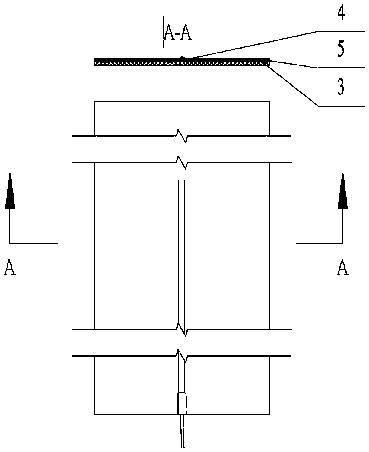
[0073] A glass fiber / epoxy resin composite substrate type fiber grating sensor, its structure is as follows figure 1 As shown in a and 1b, it includes: glass fiber / epoxy resin composite material substrate 2; polymer non-woven fabrics 3, 5; fiber grating string 4 loaded on the upper surface of glass fiber / epoxy resin composite material substrate 2; covered on The upper dry glass fiber cloth 6; and the fiber unidirectional bundle 17 wrapped around the grid area.

[0074] Specifically:

[0075] The glass fiber / epoxy resin composite substrate 2 is located at the bottom of the entire fiber grating sensor, its upper surface is used to load the fiber grating string 4, and its lower surface is pasted on the structure to be tested. The glass fiber / epoxy resin composite material substrate 2 mainly plays the role of positioning, loading the fiber grating string 4 and transferring the strain of the measured structural member to the grating area, which requires that the substrate should h...

Embodiment 2

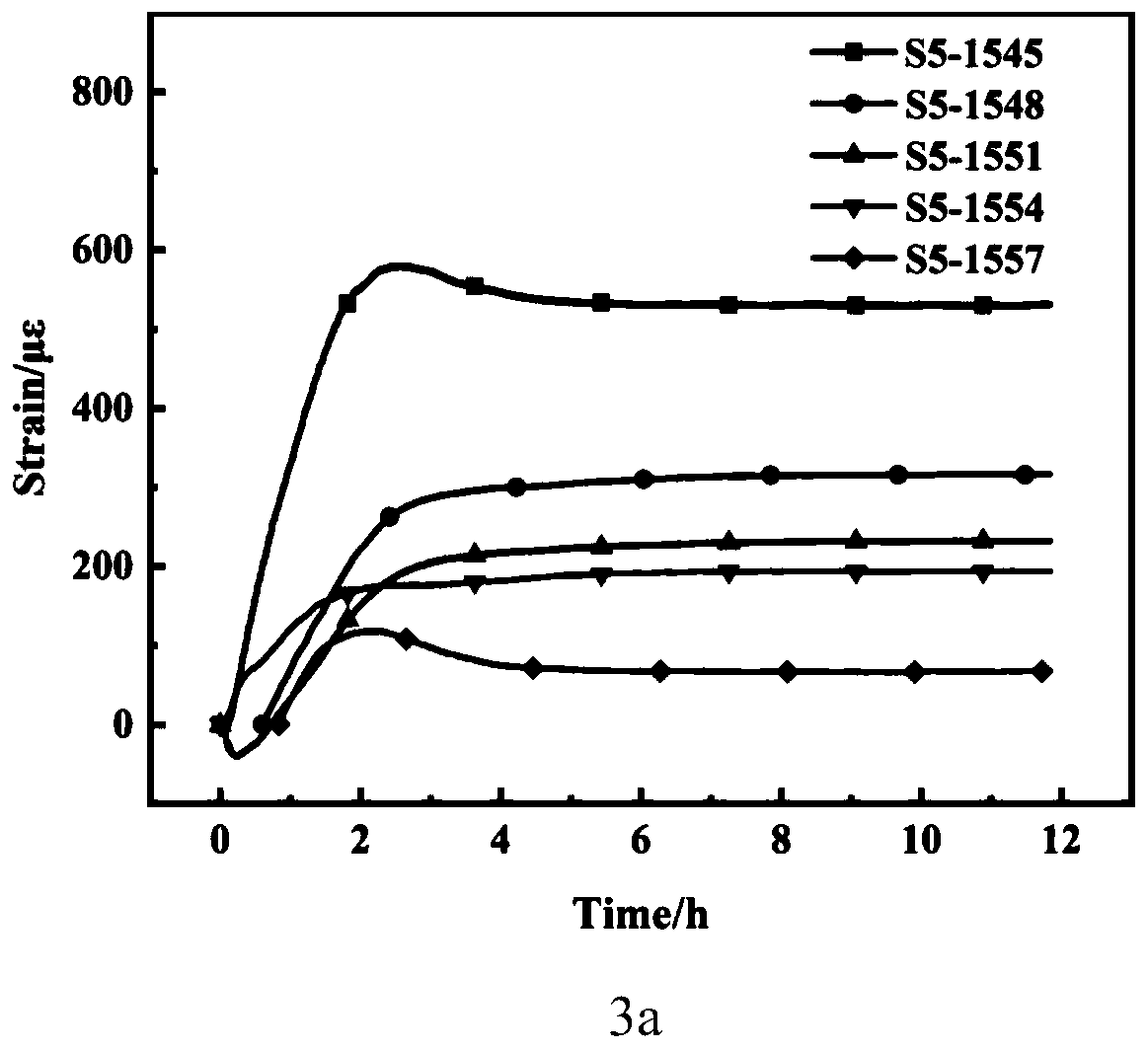
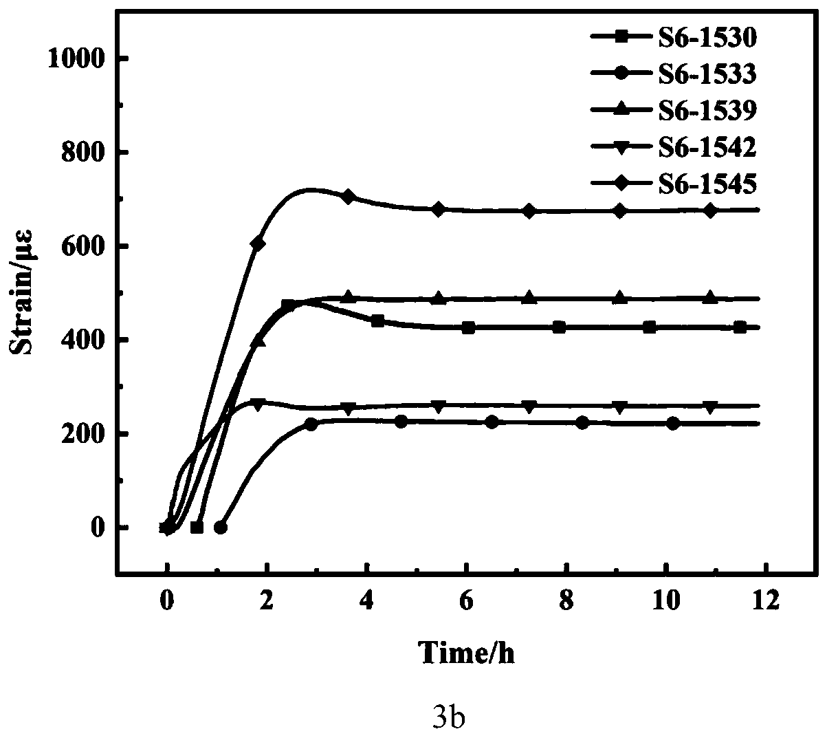
[0094] The difference from Example 1 is that the polymer non-woven fabric is made of PEEK (polyether ether ketone) non-woven fabric. Using the glass fiber / epoxy resin composite substrate type FBG sensor manufactured in this example, the center wavelength change of the FBG reflected light in the curing stage during the manufacturing process of the wind power blade mold was actually measured. The FBG sensor can detect the mold The strain conditions at different positions improve the survival rate of the sensor, avoid the chirp phenomenon, and have high test stability and test accuracy.


PUM

PropertyMeasurementUnit
thicknessaaaaaaaaaa

Abstract

The invention provides an embedded fiber bragg grating sensor. The embedded fiber bragg grating sensor structurally comprises a composite material substrate, dry-state fiber cloth, macromolecular non-woven fabric, a fiber one-way bundle, vacuum-poured liquid resin and a fiber bragg grating, wherein the composite material substrate is located at the bottom of the whole embedded fiber bragg gratingsensor and serves as a carrier of the fiber bragg grating sensor; the dry-state fiber cloth serves as a covering layer and is located at the top of the whole embedded fiber bragg grating sensor; the fiber bragg grating and the macromolecular non-woven fabric which are wrapped in the fiber one-way bundle are arranged between the dry-state fiber cloth and the composite material substrate, and the macromolecular non-woven fabric is located on the upper side and the lower side of the fiber bragg grating; the vacuum-poured liquid resin is distributed in an area between the composite material substrate and the dry-state fiber cloth, and after the liquid resin is cured, the liquid resin, the upper-layer dry-state fiber cloth and the bottom composite material substrate form a strong interface relation. According to the embedded fiber bragg grating sensor and the preparation method thereof, the survival rate and the long-term use stability of the embedded fiber bragg grating sensor are improved, and the problem that a blade mold is difficult to monitor on line is solved.

Description

technical field [0001] The invention relates to the technical fields of material preparation and optical fiber communication, in particular to an in-planted optical fiber grating sensor and a preparation method thereof. Background technique [0002] The information disclosed in this background section is only intended to increase the understanding of the general background of the present invention, and is not necessarily taken as an acknowledgment or any form of suggestion that the information constitutes the prior art already known to those skilled in the art. [0003] Since entering the 21st century, wind power, as a clean energy with the most development potential, has been paid more and more attention by countries all over the world. At present, my country has become the largest and fastest-growing market for wind power generation in the world. [0004] Wind turbine blades are one of the key core components for wind turbines to convert wind energy into mechanical energy...

Claims


Application Information

Patent Timeline
Patent Type & Authority Applications(China)
IPC IPC(8): B29C70/36G01D5/353
CPCB29C70/36G01D5/353G01D5/35354
Inventor 张雷达黄尚洪贾玉玺李义全陈忠丽刘安娜刘惠刘晓彬
Owner SHANDONG UNIV
Learn More