Motor shaft surface coating structure applied to power tool turret

A surface coating, power turret technology, applied in the tool holder accessories, electromechanical devices, electrical components and other directions, can solve problems such as damage, entering the bearing and motor inside the headstock, to extend the service life and enhance the bearing capacity , the effect of excellent lubricity

Pending Publication Date: 2020-06-19
PINGHU HAICHEN MACHINE
View PDF0 Cites 2 Cited by
  • Summary
  • Abstract
  • Description
  • Claims
  • Application Information

AI Technical Summary

Problems solved by technology

[0002] The power turret is one of the functional components of the CNC lathe. The power tool is installed on the turret for cutting. Therefore, the motor for driving the tool rotation needs to be installed on the turret. At present, the more advanced structure of the turret installs the motor inside the cutter head. In the spindle box, the motor shaft is coaxial with the tool mounting hole, which directly drives the tool to rotate for cutting. This structure simplifies the transmission size chain and can effectively reduce the adverse effects of temperature rise and noise. However, since the motorized spindle is installed inside the cutter head During the working process, the cutting fluid may enter the interior of the spindle box through both ends of the spindle and cause damage to the bearing and motor

Method used


Image

  • Motor shaft surface coating structure applied to power tool turret

Examples


Embodiment 1

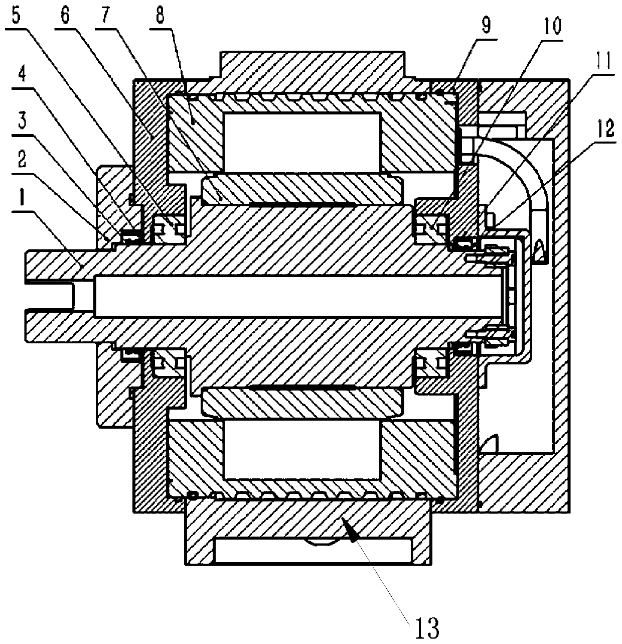
[0027] Such as figure 1 As shown, a motor shaft surface coating structure for a power turret provided in this embodiment includes a main shaft 1, a front bearing 5 and a rear bearing 10 assembled on both sides of the main shaft 1, and the main shaft 1 is composed of front bearings 5 ​​at both ends. Supported with the rear bearing 10 and form an axial positioning, the outer sides of the front bearing 5 and the rear bearing 10 are respectively connected with the front flange 6 and the rear flange 9; the front flange 6 and the rear flange 9 are installed on the headstock 13 both ends; the outer side of the front flange 6 is equipped with an end cover 2, and the front oil seal 4 and the rear oil seal 11 are respectively installed in the end cover 2 and the rear flange 9; the oil seal lips of the front oil seal 4 and the rear oil seal 11 are connected with the The outer circle of the main shaft 1 contacts and slides, and the contact areas between the main shaft 1 and the front oil ...

Embodiment 2

[0034] Front wear-resistant coating 3 and rear wear-resistant coating 12 in the present embodiment are MoS2 coating; Because MoS2 coating has very high binding force, coating is dense, seamless, even under impact or collision also can Ensure that the coating does not fall off, does not peel off, and is firmly bonded. The hardness can reach 7H and the service life is long.

[0035] MoS2 coating has excellent lubricity, compression resistance, corrosion resistance, low temperature and thermal stability, etc., and is resistant to fatigue wear, erosion wear, abrasive wear, and adhesive wear.

[0036] The friction coefficient of MoS2 coating can be as low as 0.06-0.08, which can prevent the bite, reduce resistance, wear, and seizure between parts. It is applicable to a wide range of temperature, load and speed, and it performs particularly well in high-load applications. .

[0037]The MoS2 coating can withstand a high temperature of 400°C, and will not cause peeling, cracking, dis...

Embodiment 3

[0041] The front wear-resistant coating 3 and the rear wear-resistant coating 12 in this embodiment are a kind of in titanium nitride coating, titanium carbide nitride coating and chromium nitride coating; The direct contact between metals on the inner wall of the oil seal can have a good initial wear reduction effect and prolong the service life of the main shaft; at the same time, the wear-resistant coating also helps to enhance the bearing capacity of the main shaft; specifically, in this embodiment, The thickness of the front wear-resistant coating 3 and the rear wear-resistant coating 12 is 4 μm.

[0042] For other contents of this embodiment, reference may be made to Embodiment 1 or Embodiment 2.


PUM


Abstract

The invention relates to a motor shaft surface coating structure applied to a power tool turret. The motor shaft surface coating structure comprises a main shaft, a front bearing and a rear bearing, wherein the front bearing and the rear bearing are assembled on the two sides of the main shaft. The main shaft is supported by the front bearing and the rear bearing at the two ends and forms axial positioning; the outer side of the front bearing and the outer side of the rear bearing are connected with a front flange plate and a rear flange plate respectively; the front flange plate and the rearflange plate are mounted at two ends of the main shaft box; an end cover is installed on the outer side of the front flange plate; a front oil seal and a rear oil seal are installed in the end cover and the rear flange plate respectively; oil seal lips of the front oil seal and the rear oil seal are in contact with the outer circle of the main shaft and are in sliding friction with the outer circle of the main shaft; a front wear-resistant coating and a rear wear-resistant coating are respectively arranged on contact areas of the main shaft and the front oil seal and the main shaft and the rear oil seal. According to the invention, the coating structure is compact in structure; the problem that the main shaft is difficult to seal due to the fact that the main shaft box is arranged in a cutter head structure is solved; and the service life of the sealing structure can be greatly prolonged especially when the main shaft rotates at high speed.

Description

technical field [0001] The invention belongs to the technical field of power turrets, and in particular relates to a motor shaft surface coating structure for power turrets. Background technique [0002] The power turret is one of the functional components of the CNC lathe. The power tool is installed on the turret for cutting. Therefore, the motor for driving the tool rotation needs to be installed on the turret. At present, the more advanced structure of the turret installs the motor inside the cutter head. In the spindle box, the motor shaft is coaxial with the tool mounting hole, which directly drives the tool to rotate for cutting. This structure simplifies the transmission size chain and can effectively reduce the adverse effects of temperature rise and noise. However, since the motorized spindle is installed inside the cutter head During the working process, the cutting fluid may enter the interior of the spindle box through both ends of the spindle and cause damage t...

Claims


Application Information

Patent Timeline
Patent Type & Authority Applications(China)
IPC IPC(8): H02K5/16H02K5/124B23B25/04
CPCB23B25/04H02K5/124H02K5/161
Inventor 姚向东邹运胡晓东姚洁杨柳顾春明涂磊淼谢晓杰
Owner PINGHU HAICHEN MACHINE
Why Eureka
Try Eureka