Slag waste heat recycling device

A waste heat recovery and slag technology, applied in fluid heaters, heat exchange equipment, indirect heat exchangers, etc., can solve the problems of affecting the efficiency of waste heat recovery and utilization, damage to the discharge conveyor belt, and low work efficiency, so as to reduce heat loss, The effect of slowing down the loss of heat and improving the utilization efficiency

Inactive Publication Date: 2020-06-23
黄福明
View PDF0 Cites 1 Cited by
  • Summary
  • Abstract
  • Description
  • Claims
  • Application Information

AI Technical Summary

Problems solved by technology

[0002] During the use of the boiler, a large amount of slag will be produced, and these slags contain high heat. Directly using the discharge conveyor belt to output will not only damage the discharge conveyor belt, but also cause waste of heat. It is necessary to use the waste heat recovery device to clean the slag. heat recovery
[0003] The existing slag waste heat recovery and utilization device does not have a discharge assembly, and manpower is needed to remove the low-temperature slag whose waste heat has been recycled in time. Not only is the labor intensity high, the work efficiency is low, and the accumulation of low-temperature slag will absorb the heat of the high-temperature slag, Affect the recycling efficiency of waste heat

Method used


Image

  • Slag waste heat recycling device
  • Slag waste heat recycling device
  • Slag waste heat recycling device

Examples


Embodiment 1

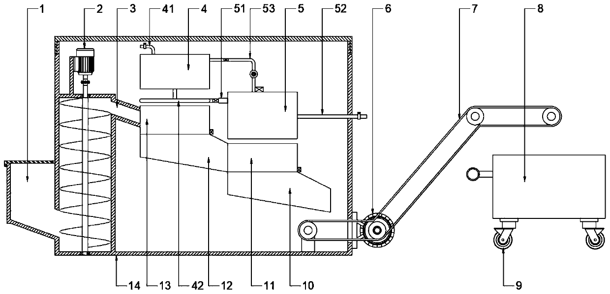
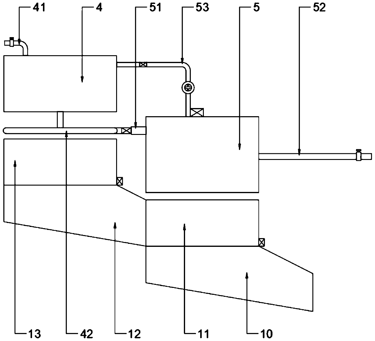
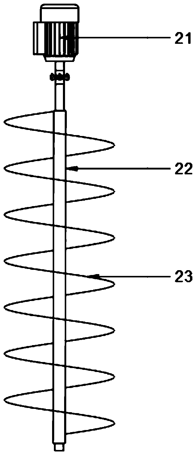
[0026] see Figure 1~4 , in an embodiment of the present invention, a slag waste heat recovery and utilization device includes a box body 14 and a waste heat recovery mechanism arranged inside the box body 14, and a feeding hopper 1 is connected to one side of the box body 14 and the feeding hopper 1 is rotatably provided with a feed door, which can effectively prevent the dust from overflowing during the process of conveying the slag, and the feed hopper 1 and the feed door are both made of heat insulating materials, which can slow down Dissipate, improve the utilization efficiency, and prevent the heat from being transferred to the feed hopper 1 and the feed door to burn the operator; the waste heat recovery mechanism includes a material conveying component 2 and a waste heat utilization component, and the material conveying component 2 is set in the box body 14 and its bottom is communicated with the feed hopper 1, and the discharge end of the conveying component 2 is provi...

Embodiment 2

[0036] see figure 1 , in the embodiment of the present invention, a slag waste heat recovery and utilization device, in order to improve the waste heat utilization rate and safety of the device, on the basis of embodiment 1, the top of the box 14 is provided with an upper cover, when used for a period of time Finally, open the upper cover to clean the inner wall of the box body 14 and the internal parts to prevent too much dirt and absorb the waste heat of the slag; the side walls of the box body 14 and the upper cover are hollow structures and the hollow structures are filled with Asbestos insulation reduces the heat loss of the slag, improves the recovery of waste heat from the slag, and avoids damage to operators caused by heat overflow.

[0037] The working principle of the present invention is:

[0038] When working, add water to the inside of the heating water tank 4 through the first water inlet pipe 41 to keep the water level above the minimum water level. The water o...


PUM


Abstract

The invention discloses a slag waste heat recycling device. The slag waste heat recycling device comprises a box body, and a conveying assembly and a waste heat utilizing assembly which are arranged in the box body. The conveying assembly is arranged in the box body, and the bottom of the conveying assembly communicates with a feed hopper. The discharge end of the conveying assembly is provided with a material guide pipe communicating with the waste heat utilizing assembly. The side, away from the feed hopper, of the box body is further provided with a discharging assembly, and the feeding endof the discharging assembly is located on the lower side of the discharging end of the waste heat utilizing assembly. The slag waste heat recycling device is filled with a thermal insulation materialand thermal insulation asbestos, the slag heat loss is reduced, the recycling efficiency is improved, and meanwhile the injuries caused by overflow heat to operators are avoided; a cylinder closely sleeves the periphery of a feeding spiral blade, so that slag is prevented from falling from a seam, and meanwhile a conveying motor is isolated and protected; by means of a reflux pipe with a water pump and a second water temperature sensor, the temperature of hot water is ensured; and by means of a slag temperature sensor, slag not meeting the temperature requirement is conveyed to a next link intime.

Description

technical field [0001] The invention relates to a waste heat recovery and utilization device, in particular to a slag waste heat recovery and utilization device. Background technique [0002] During the use of the boiler, a large amount of slag will be produced, and these slags contain high heat. Directly using the discharge conveyor belt to output will not only damage the discharge conveyor belt, but also cause waste of heat. It is necessary to use the waste heat recovery device to clean the slag. Heat is recycled. [0003] The existing slag waste heat recovery and utilization device does not have a discharge assembly, and manpower is needed to remove the low-temperature slag whose waste heat has been recycled in time. Not only is the labor intensity high, the work efficiency is low, and the accumulation of low-temperature slag will absorb the heat of the high-temperature slag, Affect the recycling efficiency of waste heat. Contents of the invention [0004] The object ...

Claims


Application Information

Patent Timeline
Patent Type & Authority Applications(China)
IPC IPC(8): F23J1/00F24H9/14F24H9/18F28D21/00F28F27/00
CPCF23J1/00F24H9/14F24H9/1809F28D21/00F28F27/00
Inventor 黄福明
Owner 黄福明
Why Eureka
Try Eureka