Limestone-wet flue gas desulfurization defoaming method for thermal power plant based on desulfurization defoaming agent

A technology for wet flue gas desulfurization and defoaming agent, applied in separation methods, chemical instruments and methods, gas treatment, etc., can solve problems such as increased wind resistance and pressure difference, hidden dangers of equipment safety, and large amount of foaming.

Pending Publication Date: 2020-06-26
陕西页川电力科技有限公司
View PDF5 Cites 5 Cited by
  • Summary
  • Abstract
  • Description
  • Claims
  • Application Information

AI Technical Summary

Problems solved by technology

[0004] (1) SO2 does not react with limestone and escapes directly with flue gas, resulting in a decrease in desulfurization efficiency and even SO2 emissions exceeding the standard
[0005] (2) Severe fouling of GGH and demister, reduced flue gas flow area, increased wind resistance and pressure difference, which will cause blockage of GGH and demister and equipment safety hazards in serious cases, forcing the generator set to reduce load, and even cause The desulfurization system tripped and the generator set was forced to shut down
[0006] The difficulty in solving the above technical problems lies in: (1) The flue gas desulfurization systems of domestic thermal power plants (thermal units, steelmaking plants and coking plants) all adopt the limestone-wet desulfurization production process. The biggest defect of this production process is that it cannot solve the problem of limestone Serum Foaming Problems
[0007] (2) The hidden dangers of production safety and excessive environmental protection emissions caused by limestone slurry foaming cannot be solved at present
[0008] (3) Due to the high flue gas temperature, large flue gas volume, complex causes of foaming, irregular foaming, large foaming volume, and fast foaming speed, the damage caused is relatively serious. The existing technology cannot dynamically analyze and detect the absorption tower. The foaming process of the internal limestone slurry, the current domestic desulfurization system cannot eliminate the above problems, and there is no corresponding technology that can solve the above problems

Method used


Image

  • Limestone-wet flue gas desulfurization defoaming method for thermal power plant based on desulfurization defoaming agent

Examples


Embodiment Construction

[0032] In order to further understand the content, features and effects of the present invention, the following examples are given, and detailed descriptions are given below with reference to the accompanying drawings.

[0033] Aiming at the problems existing in the prior art, the present invention provides a limestone-wet flue gas desulfurization and defoaming method for thermal power plants (municipal coal-fired heating units, steelworks and coking plants) based on a special defoamer for desulfurization, combined below Accompanying drawing describes the present invention in detail.

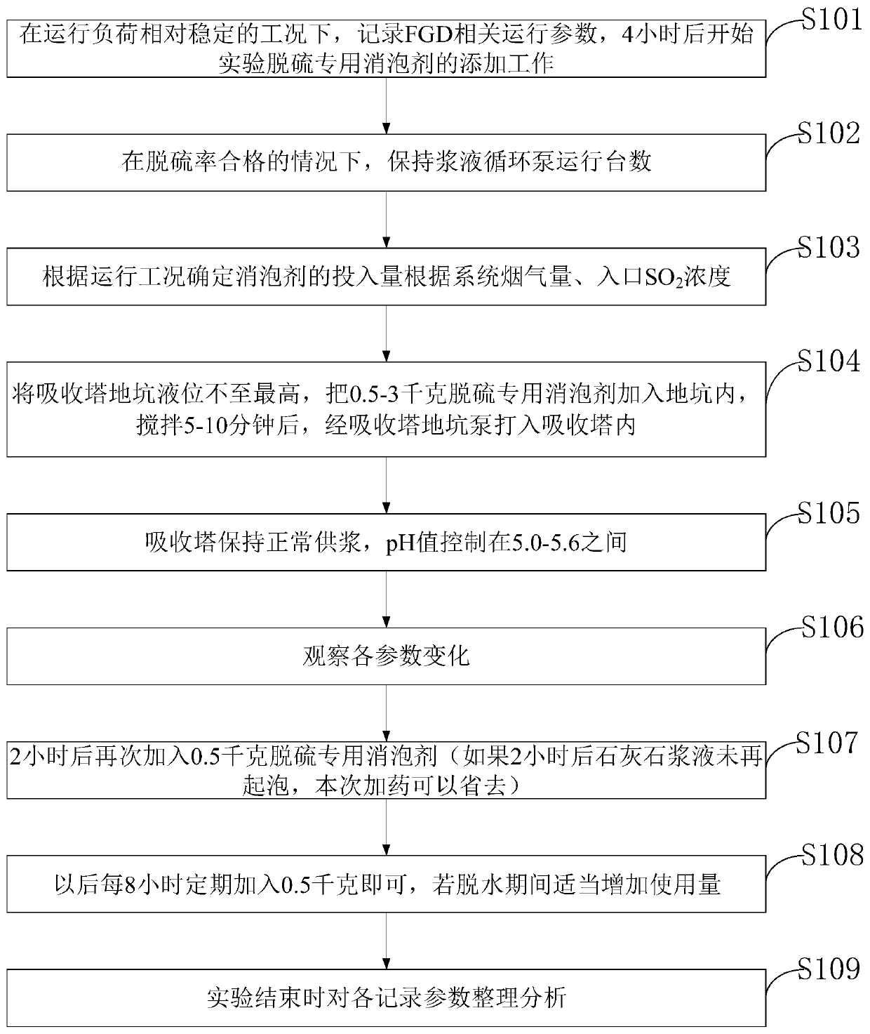
[0034] Such as figure 1 As shown, the desulfurization defoamer based thermal power plant limestone-wet flue gas desulfurization absorption tower limestone slurry defoaming method provided by the embodiment of the present invention includes the following steps:

[0035] S101. Under the condition of relatively stable operating load, record the relevant operating parameters of FGD, and start the e...


PUM


Abstract

The invention belongs to the technical field of flue gas desulfurization, and discloses a limestone-wet flue gas desulfurization defoaming method for a thermal power plant based on a desulfurization defoaming agent. The method comprises the following steps: recording FGD related operation parameters under the working condition of relatively stable operation load, and starting the addition work ofa special defoaming agent for experimental desulfurization after 4 hours; under the conditions that the desulfurization rate is qualified and the PH value is 5.0-5.6, the running number of the slurrycirculating pumps is kept; determining the feeding amount of the defoaming agent according to the operation conditions such as the inlet flue gas amount, the flue gas dust content, the boiler oil feeding amount, the inlet SO2 concentration and the like of the desulfurization system; and adding 0.5-3kg of the special defoaming agent for desulfurization into the pit, stirring for 5-10 minutes, and pumping into an absorption tower through an absorption tower pit pump. The defoaming agent is mainly applied to defoaming of limestone slurry in limestone-wet flue gas desulfurization absorption towersof thermal power plants, municipal coal-fired heat supply units, steel mills and coking plants.

Description

technical field [0001] The invention belongs to the technical field of YC-503 desulfurization special defoamer in limestone-wet flue gas desulfurization technology field of coal-fired power plant, especially relates to a limestone-wet flue gas desulfurization and defoaming method of thermal power plant based on desulfurization defoamer, specifically a A defoaming method for limestone-wet flue gas desulfurization absorption tower limestone slurry in thermal power plants (municipal heating units, steel plants and coking plants) based on a special defoamer for desulfurization. Background technique [0002] At present, the limestone-wet flue gas desulfurization technology of the existing coal-fired power plants (municipal heating units, steel plants and coking plants) is as follows: due to the SiO contained in the coal 2 Due to insufficient combustion of particles and pulverized coal, oily substances entering the absorption tower, and oil injection during the combustion process,...

Claims


Application Information

Patent Timeline
Patent Type & Authority Applications(China)
IPC IPC(8): B01D19/04B01D53/80B01D53/50
CPCB01D19/04B01D53/502B01D2251/404B01D2251/602B01D2258/0283
Inventor 孙丽萍
Owner 陕西页川电力科技有限公司
Why Eureka
Try Eureka