Check patentability & draft patents in minutes with Patsnap Eureka AI!

Micro-particle suspension volume concentration micro-fluidic device

A micro-particle and micro-fluidic technology, applied in fluid controllers, laboratory equipment, laboratory containers, etc., can solve the problems of filter membrane clogging efficiency, biological particle damage, death, etc., and achieve high cell activity and high High concentration and low cell damage

Inactive Publication Date: 2020-06-26
SOUTHEAST UNIV
View PDF7 Cites 6 Cited by
  • Summary
  • Abstract
  • Description
  • Claims
  • Application Information

AI Technical Summary

Problems solved by technology

However, the centrifugation method is expensive and cannot be used in complex working conditions such as the field. At the same time, it is not capable of efficiently concentrating samples with extremely low cell / particle concentration or super-large volume samples, and strong centrifugal force will cause damage and death of biological particles such as cells.
Membrane filtration uses filter holes of specific pore size on the filter membrane to block cells or particles, and increase the concentration of the sample by filtering out the blank liquid. This method is simple and direct, but it is difficult to recover cells blocked on the filter membrane. The clogging problem will cause the efficiency to decrease sharply with the use time, and the fixed filter hole is only suitable for the filtration of cells or particles of a specific size, and the scope of application is small

Method used


Image

  • Micro-particle suspension volume concentration micro-fluidic device
  • Micro-particle suspension volume concentration micro-fluidic device
  • Micro-particle suspension volume concentration micro-fluidic device

Examples


Embodiment 1

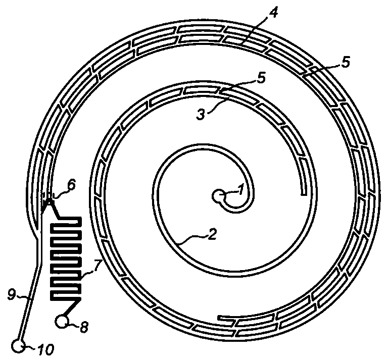
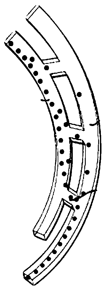
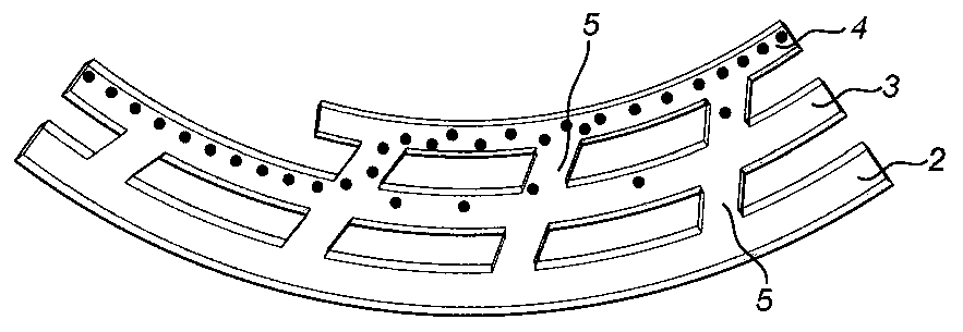
[0017] like figure 1 As shown, the micro-particle suspension volume concentration microfluidic device is composed of a sample inlet 1, a series of spiral flow channels, a cross-flow filter flow channel 5, a Y-shaped bifurcated flow channel 6, a concentrated sample outlet 8 and a blank liquid outlet 10 connected. The confluence flow channel 9 is composed of a series of spiral flow channels connected to the sample inlet 1, and a cross-flow filter flow channel 5 is arranged between the series of spiral flow channels. The end of the series of spiral flow channels includes a sample outlet and a liquid outlet. 6 is connected to the sample outlet at the end of the series of spiral flow channels, the concentrated sample outlet 8 is connected to the Y-shaped bifurcated flow channel 6 through the S-shaped flow resistance flow channel unit 7, and the confluence flow channel 9 is connected to the liquid outlet at the end of the series of spiral flow channels connection; the cross-section ...

Embodiment 2

[0022] Compared with Example 1, this embodiment differs in that the cross-section height of the series of spiral flow channels is 150 μm, and the sample solution to be concentrated of human breast cancer cell MCF-7 with 15 μm, 20 μm particles and 20 μm in diameter is prepared, and the sample solution is prepared at 3 ml / The volume flows of min, 3.5ml / min, 4ml / min, 4.5ml / min, 5ml / min, 5.5ml / min, and 6ml / min are injected into the micron particle suspension volume concentration microfluidic device from the sample inlet 1.

[0023] As shown in Figure 6(a), 15 μm particles can achieve the best concentration effect at a volume flow rate of 4 ml / min, and the best concentration ratio is 12.17, and the best concentration ratio of 20 μm particles at a volume flow rate of 5 ml / min is 12.49 , the best recovery rate of 15 μm particles shown in Figure 6(b) is 97.33%, and the best recovery rate of 20 μm particles is 99.99%.

[0024] As shown in Figure 7 (a), the best concentration ratio obt...

Embodiment 3

[0026] The difference between this embodiment and Embodiment 1 is that the concentrated sample outlet 8 is connected to the Y-shaped bifurcated flow channel 6 through the sinusoidal line-shaped concentrated flow channel 13 and the cross-shaped three-fork outlet system 14, and the sinusoidal line-shaped concentrated flow channel 13 is used to connect the The micron particles are focused to the middle area of ​​the flow channel, and the blank liquid on both sides is removed by means of the three-fork outlet system 14 to further improve the concentration effect. The structure is as follows: Figure 4 shown.

[0027]The device is used to concentrate MCF-7 cells and A549 lung cancer cells with concentrated sample solution. The concentration of MCF-7 cells achieves the best concentration effect at a volume flow rate of 4ml / min, the best concentration ratio is 41, and the concentration of A549 lung cancer cells in The best concentration ratio obtained under the volume flow rate of 4m...


PUM


Abstract

The invention discloses a micro-particle suspension volume concentration micro-fluidic device, which is composed of a sample inlet, series spiral flow channels, a cross-flow filtering flow channel, aY-shaped bifurcated flow channel, a concentrated sample outlet and a confluence flow channel connected with a blank liquid outlet, wherein the sample inlet is connected with the series spiral flow channels, the cross-flow filtering flow channel is arranged between the series spiral flow channels, the tail ends of the series spiral flow channels comprise a sample outlet end and a liquid outlet end,the Y-shaped bifurcated flow channel is connected to the sample outlet ends of the tail ends of the series spiral flow channels, the concentrated sample outlet is connected with the Y-shaped bifurcated flow channel, and the confluence flow channel is connected with the liquid outlet end of the tail ends of the series spiral flow channels. The device can realize high-flux and high-magnification concentration of a micron particle suspension, the optimal recovery rate is as high as 99.99%, precise flow resistance matching is not needed, the operation is simple, the damage to cells is low, the activity of the treated cells is as high as 95%, the structure is simple, and the cost is low.

Description

technical field [0001] The present invention relates to a volume concentration microfluidic device, more particularly, to a micron particle suspension volume concentration microfluidic device. Background technique [0002] Biological suspensions containing cells or particles are important medical samples. The counting and detection of cells or particles in these biological suspensions can provide important information for disease diagnosis. The detection of cells or particles in biological suspensions requires sample Concentration pretreatment improves the sensitivity and detection rate of detection by increasing the concentration of target components in the sample. Currently, the commonly used sample concentration methods include: high-speed centrifugation and membrane filtration. The centrifugation method uses strong centrifugal force to force the cells or particles to settle to the bottom of the centrifuge tube, and then removes the supernatant to reduce the sample volume...

Claims


Application Information

Patent Timeline
IPC IPC(8): B01L3/00
CPCB01L3/5027B01L3/50273B01L3/502761B01L2200/0636B01L2200/0647B01L2300/0681B01L2300/0883B01L2400/0409
Inventor 项楠倪中华
Owner SOUTHEAST UNIV
Features
  • R&D
  • Intellectual Property
  • Life Sciences
  • Materials
  • Tech Scout
  • Unparalleled Data Quality
  • Higher Quality Content
  • 60% Fewer Hallucinations
Learn More