Eureka AIR delivers breakthrough ideas for toughest innovation challenges, trusted by R&D personnel around the world.

Method for simulating fatigue hysteresis loop of ceramic-based composite material in high-temperature environment

A composite material, high temperature environment technology, applied in the field of material mechanics, can solve the problems of no oxidation morphology research, inability to calculate the fatigue loading hysteresis loop of SiC/SiC composite materials, and no consideration of the oxidation behavior of ceramic matrix composite materials.

Pending Publication Date: 2020-06-26
NANJING UNIV OF AERONAUTICS & ASTRONAUTICS
View PDF3 Cites 2 Cited by
  • Summary
  • Abstract
  • Description
  • Claims
  • Application Information

AI Technical Summary

Problems solved by technology

Patent application CN110096732A "A Method for Predicting Residual Stiffness of Ceramic Matrix Composites in Stress Oxidation Environment", CN109992850A "Prediction Method for Residual Tensile Strength of Ceramic Matrix Composite Materials in Stress Oxidation Environment", CN110096731A "A Ceramic Matrix Composite A method for predicting mass change in an oxidizing environment” proposed an oxidation kinetics model in a high-temperature oxidizing environment. Based on this model, the oxygen concentration at different positions inside the material, the interface consumption length, and the surface oxide layer of the SiC fiber at the crack were calculated. Thickness changes with stress, temperature and time, determine the size of oxidation defects on the surface of SiC fibers and derive the expression of characteristic strength distribution of SiC fibers, but the research is on the oxidation morphology under creep stress oxidation environment, and there is no analysis of the oxidation defects under fatigue loading. Oxidation morphology was studied
The literature "Complex Prefabricated Ceramic Matrix Composites Fatigue Failure Mechanism and Multi-scale Simulation" mainly studies the fatigue failure of ceramic matrix composites, and proposes an interface friction slip model. The distribution of the slip zone at the material interface, but the oxidation behavior of ceramic matrix composites in high temperature environments is not considered in the calculation of fatigue failure
The literature "Fatigue Damage Model and Life Prediction of Long Fiber Reinforced Ceramic Matrix Composites" mainly studies the fatigue failure of ceramic matrix composites through the shear lag model, gives the calculation formula of the shear lag model, and also obtains the fiber random failure percentage by calculation , Interfacial shear stress changes with the number of cycles, but does not consider the impact of high temperature oxidation on the fatigue failure of ceramic matrix composites
The literature "Modeling the effect of oxidation onhysteresis loops of carbon fiber-reinforced ceramic-matrix composites underwater fatigue at elevated temperature" mainly studies the effect of high temperature oxidation on the fatigue hysteresis dissipation energy and interfacial slip of C / SiC composites, considering the The effect of high temperature oxidation on the length of interface oxidation consumption, without considering the effect of oxidation on fiber strength, and the effect of oxidation of matrix cracks on the width of oxygen diffusion channels, and the oxidation mechanism of C / SiC and SiC / SiC in high temperature oxidation environment different, so it is impossible to calculate the fatigue loading hysteresis loop of SiC / SiC composites in high temperature oxidizing environment

Method used


Image

  • Method for simulating fatigue hysteresis loop of ceramic-based composite material in high-temperature environment
  • Method for simulating fatigue hysteresis loop of ceramic-based composite material in high-temperature environment
  • Method for simulating fatigue hysteresis loop of ceramic-based composite material in high-temperature environment

Examples


Embodiment Construction

[0092] In order to clarify the technical solution of the present invention, the present invention will be described in detail below in conjunction with the accompanying drawings and specific embodiments.

[0093]

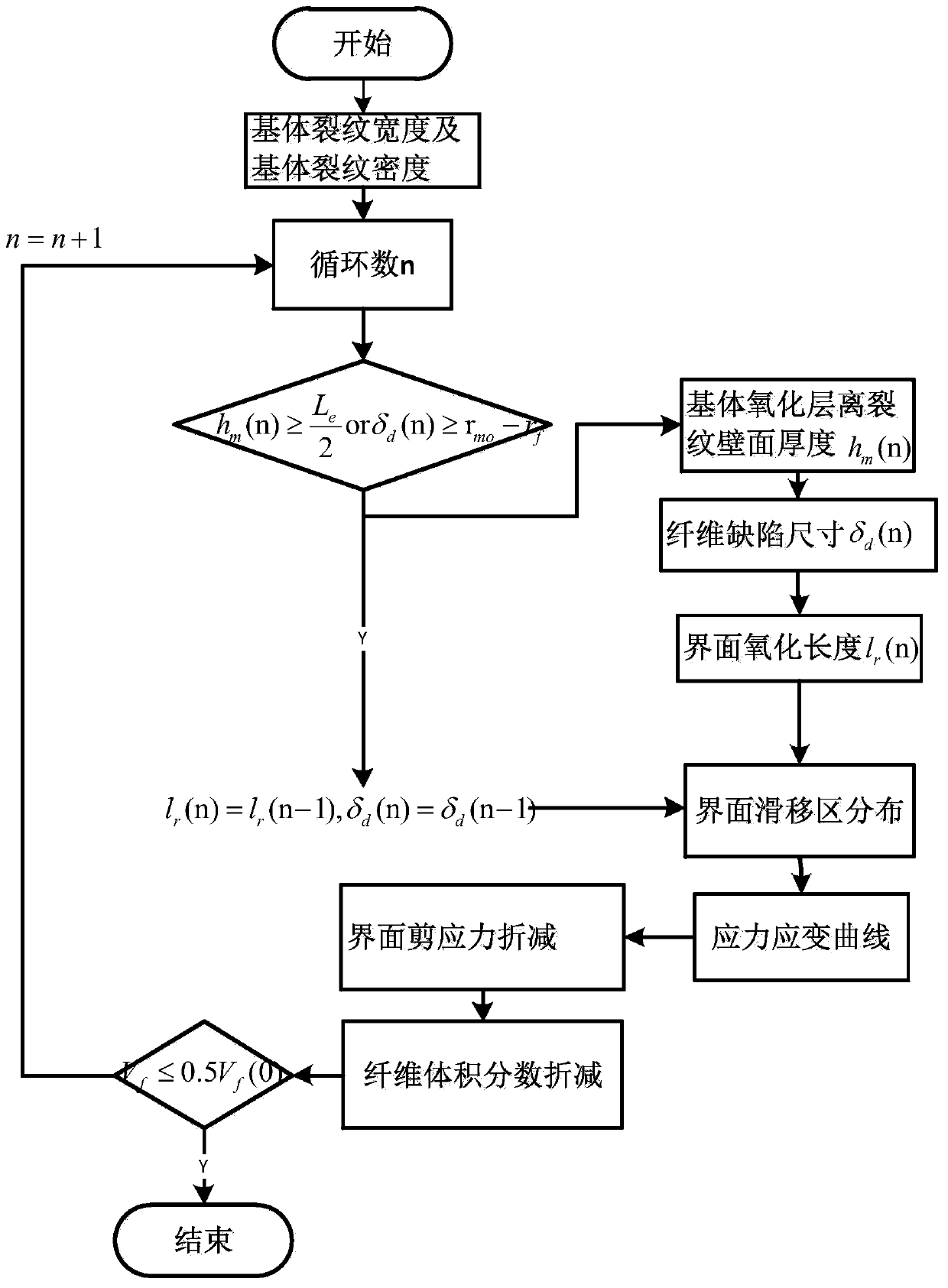
[0094] like figure 1 The simulation method of the fatigue hysteresis loop of a ceramic matrix composite material in a high temperature environment is shown, and the process is as follows:

[0095] Step 1: Determine the crack density and crack width of the saturated matrix

[0096] According to the composite uniform cracking model, such as figure 2 As shown, the average crack spacing L of the matrix is ​​calculated based on the empirical formula (1):

[0097]

[0098] Among them, σ is the applied stress, σ c is the critical cracking stress of the matrix, and β is an empirical parameter;

[0099] Take the loading external force amplitude as σ max , the stress ratio R=0, combined with the parameters, the average crack spacing of the matrix is ​​obtained L=1...


PUM

PropertyMeasurementUnit
widthaaaaaaaaaa

Abstract

The invention discloses a method for simulating a fatigue hysteresis loop of a ceramic matrix composite material in a high-temperature environment. The method comprises the following steps: determining the crack density and the crack width of a saturated matrix; determining the average width of a diffusion channel of oxygen in the cracks of the composite material matrix; determining the change rules of the thickness of the oxide layer at the crack of the matrix away from the crack wall surface, the interface oxidation length and the fiber notch radius along with the oxidation time; determiningthe change rule of the thickness of the oxide layer at the crack of the matrix away from the wall surface of the crack, the interface oxidation length and the fiber oxide layer thickness along with the loading cycle number; determining the distribution of an interface slip region and the stress-strain relationship of the composite material; determining a change rule of the interface shear stressalong with the cycle number; the . A simulation method disclosed by the invention can be used for predicting the fatigue hysteresis curve of the single-direction SiC / SiC composite material in a high-temperature oxidation environment, and accurately judging the damage of the loading stress to the ceramic matrix composite material.

Description

technical field [0001] The invention relates to the technical field of material mechanics, in particular to a method for simulating fatigue hysteresis loops of ceramic matrix composite materials in high temperature environments. Background technique [0002] Silicon carbide fiber reinforced silicon carbide ceramic matrix composites (Siliconcarbidefiber reinforcedsilicon carbide composites, hereinafter referred to as SiC / SiC) is a new type of high-temperature structural material for the hot end parts of aero-engines. Weight reduction of end parts. In the service environment, SiC / SiC composite components must bear the effect of fatigue load on the one hand, and fatigue hysteresis behavior occurs, and the stress-strain relationship is represented by a fatigue hysteresis loop. The fatigue hysteresis loop reflects the mesoscopic failure mechanism of SiC / SiC composites under cyclic loading, which is very important for analyzing the fatigue performance and life of materials. On t...

Claims


Application Information

Patent Timeline
Patent Type & Authority Applications(China)
IPC IPC(8): G06F30/20G06F119/14
Inventor 孙志刚刘炎陈西辉牛序铭高希光
Owner NANJING UNIV OF AERONAUTICS & ASTRONAUTICS
Why Eureka
Eureka Blog
Learn More