Full-coupling magnetic element

A magnetic component and full coupling technology, applied in the field of coupled inductors, can solve the problems of irregular input/output ports, circuit ripple and output current ripple not reaching the best, poor scalability, etc., to achieve good battery life Effect

Active Publication Date: 2020-06-26
杭州矽磁微电子有限公司
View PDF16 Cites 10 Cited by
  • Summary
  • Abstract
  • Description
  • Claims
  • Application Information

AI Technical Summary

Problems solved by technology

[0010]The problems of the above-mentioned multi-phase adjacent coupled inductors are: the input / output ports are irregular, the expansion is relatively poor, and the ripple of each phase circuit and the output current ripple less than optimal

Method used


Image

  • Full-coupling magnetic element
  • Full-coupling magnetic element
  • Full-coupling magnetic element

Examples


Embodiment 1

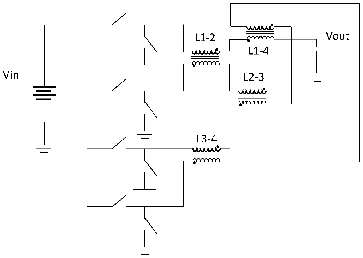
[0055] A fully coupled magnetic element, including at least two-phase circuits, each phase circuit is formed by connecting several coupling units 1, each two-phase circuit is directly coupled through at least one coupling unit 1, and the respective DC components in the two-phase circuit currents generate The direction of the magnetic field is opposite.

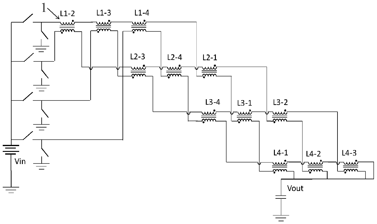
[0056] as attached figure 2 As shown, taking a 4-phase step-down switching power supply as an example, the circuit uses 12 coupling units 1, namely L1-2, L1-3, L1-4, L2-1, L2-3, L2-4, L3-1 , L3-2, L3-4, L4-1, L4-2, L4-3, the current of the first phase starts from the input end and flows through L1-2, L1-3, L1-4, L2-1 in sequence . L3-2, L4-2 reach the output end, forming the second phase current path; the third phase current starts from the input end and flows through L1-3, L2-3, L3-4, L3-1, L3 successively -2, L4-3, reaching the output end, forming the third phase current path; the fourth phase current starts from the inp...

Embodiment 2

[0061] A fully coupled magnetic element, including N rows × (N-1) columns of coupling units 1 with the same structure arranged in a matrix, the matrix is ​​recorded as: A=(a ij ) N×N-1 , where a ij is the coupling unit 1 in the i-th row and j-column of matrix A, N is a natural number ≥ 2, i=1, 2, 3,...N, j=1, 2, 3,...N-1, each coupling The unit (1) has a magnetic core 2, a forward winding coil 3 and a reverse winding coil 4, the two winding coils are wound on the magnetic core 2 or the magnetic core 2 wraps the two winding coils, the number of turns of the two winding coils The same, and the direction of the magnetic field lines generated by the coil currents of the two windings in the core 2 is opposite. The N input terminals are located on the same side of the matrix, and the N output terminals are located on the other side of the matrix. When p=1, the first input ends through a 11 , a 12 , a 13 ,...a 1(N-1) The forward winding coil 3, and then through a 2(N-1) , a ...

Embodiment 3

[0076] Other parts are as shown in embodiment 2, the difference is: as attached Figure 11a , 11b , 11c are schematic diagrams of four-phase, three-phase, and two-phase full-coupling magnetic components in this embodiment, wherein the magnetic core 2 is a closed loop, which can form a closed magnetic flux loop and increase the inductance per unit area.


PUM

PropertyMeasurementUnit
thicknessaaaaaaaaaa
thicknessaaaaaaaaaa

Abstract

The invention relates to the technical field of coupling inductors, and particularly relates to and discloses a full-coupling magnetic element, which comprises at least two phases of circuits. Each phase of circuit is formed by connecting a plurality of coupling units, each two phases of circuits are directly coupled through at least one coupling unit, and the directions of magnetic fields generated by respective direct current components in the currents of the two phases of circuits are opposite. According to the full-coupling magnetic element, all phases are directly coupled to one another,and low output current ripples are achieved; the integrated full-coupling magnetic element has very high regularity and expandability, and has the advantages of small size, low cost, strong expansibility and high integration; and the full-coupling magnetic element can be integrated with a peripheral semiconductor chip into a single chip, or the full-coupling magnetic element can be directly manufactured on a wafer which is provided with a semiconductor chip in advance, so that a micro power supply management chip which is highly integrated and does not need an external magnetic passive deviceis formed, and the micro power supply management chip can replace traditional circuits and schemes such as power supply management based on discrete components, and is applied to multiple purposes.

Description

technical field [0001] The invention relates to the technical field of coupled inductors, in particular to a fully coupled magnetic element. Background technique [0002] With the continuous increase of the functions of electronic products, the number of switching power supplies in electronic products continues to increase, while the volume of electronic products is constantly shrinking, which makes the volume of switching power supplies need to be continuously reduced, and at the same time must meet high efficiency, so as to ensure Better battery life for electronics. Traditional switching power supplies use pre-fabricated single-stand magnetic components. Single stand-alone magnetic components are large in size and low in integration, so it is difficult to reduce the size of the switching power supply, which prevents the size of electronic products from being greatly reduced, hindering the miniaturization of the power supply. At the same time, it is not conducive to impro...

Claims


Application Information

Patent Timeline
Patent Type & Authority Applications(China)
IPC IPC(8): H01F38/14H01F27/30H01F27/24H01F27/32H01F27/28H01F27/29
CPCH01F38/14H01F27/306H01F27/245H01F27/324H01F27/2804H01F27/29H01F2027/2809H02M1/14H01F17/0033H01F2017/065H01F37/00H02M3/158H02M3/1586H01F27/24H01F27/2847
Inventor 王宁宁彭善峰俞俊超启荣.菲尼叶挺聪
Owner 杭州矽磁微电子有限公司
Why Eureka
Try Eureka