Heating method for mixing-heat-supplement-type lithium bromide heat pump
A lithium bromide and heat pump technology, applied in heat pumps, heating methods, household heating, etc., can solve problems such as discarding, and achieve the effect of saving and fully utilizing water sources and heat
- Summary
- Abstract
- Description
- Claims
- Application Information
AI Technical Summary
Problems solved by technology
Method used
Image

Examples
Embodiment 1
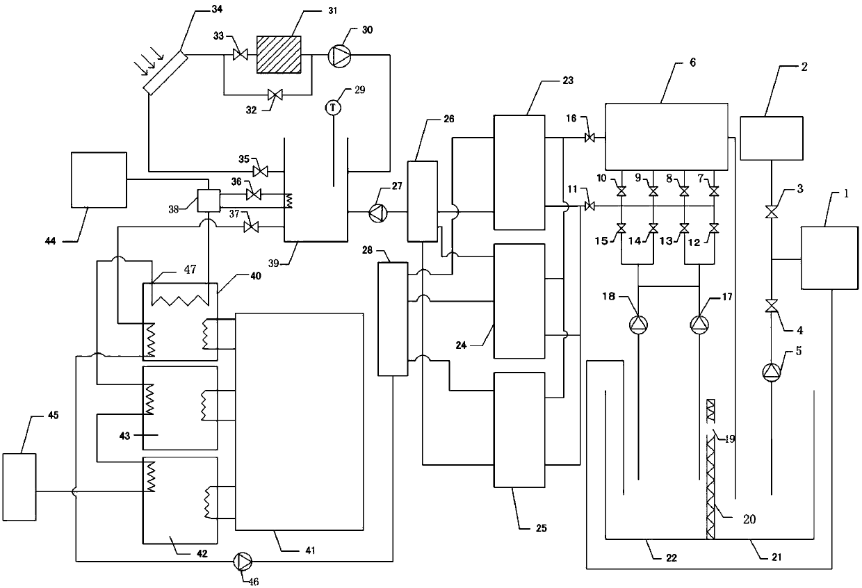
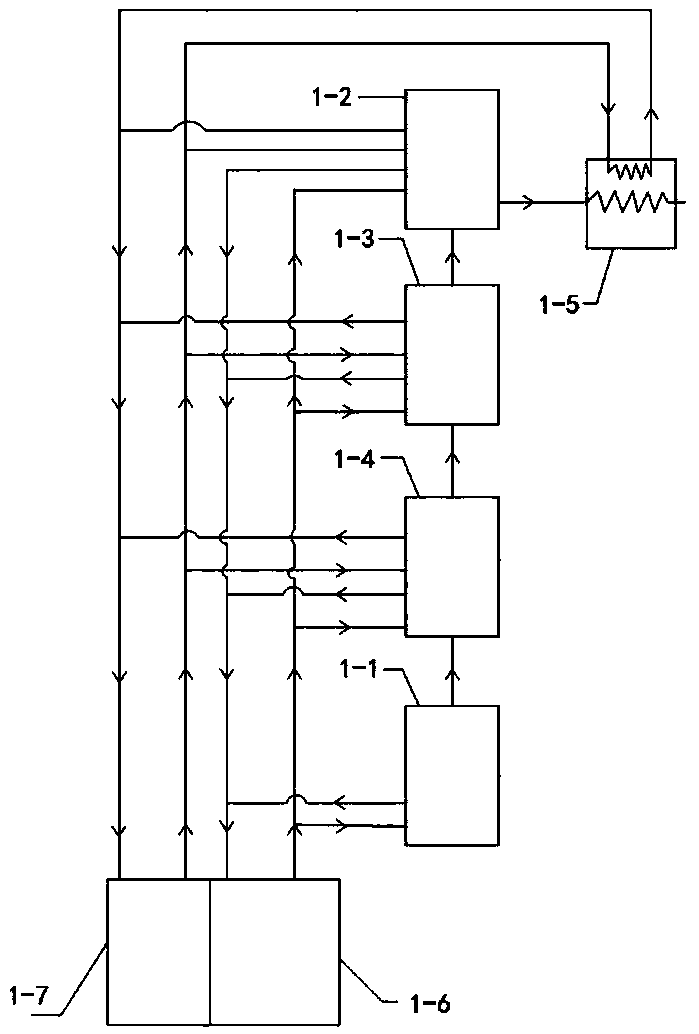
[0019] Embodiment 1: A heating system integrating multiple waste heat couplings, including a float glass waste heat recovery device, a solar waste heat recovery device and a lithium bromide heat pump heating device.
[0020] The float glass waste heat recovery device includes a float glass workshop (1), a hot pool (22), a cold pool (21), a second circulation pump (17), a third circulation pump (18) and two-stage control valves, The cooling tower (6), the heat pump, the first water outlet of the float glass workshop (1) is led into the heat pool (22) by the first water pipe, the inlet of the cooling tower (6) is connected to the upper water pipe, and the outlet of the cooling tower (6) The pipeline leads to the cold pool (21), the upper water pipe is equipped with a two-stage control valve and a circulating pump, the upper water pipe leads to the hot pool (22), and the circulating pump is arranged between the hot pool (22) of the upper water pipe and the two-stage control valve ...
PUM
 Abstract
Description
Claims
Application Information