
Single-phase high-gain photovoltaic grid-connected inverter with continuous input current and control method

A technology with input current and high gain, applied in the direction of converting AC power input to DC power output, photovoltaic power generation, single-grid parallel feeding arrangement, etc. , the effect of reducing the filter capacitance

Active Publication Date: 2021-05-14
NANTONG UNIVERSITY
View PDF15 Cites 0 Cited by
  • Summary
  • Abstract
  • Description
  • Claims
  • Application Information

AI Technical Summary

Problems solved by technology

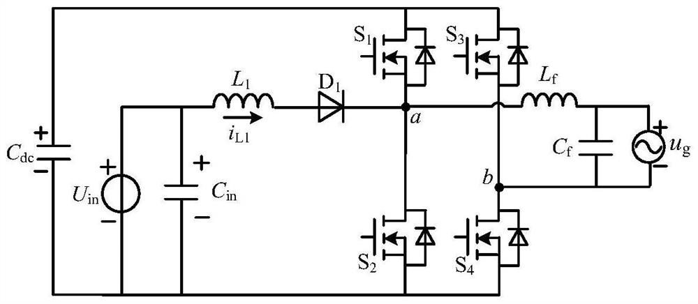
With this modulation strategy, figure 1 The single-phase integrated inverter shown can better solve the DC bus voltage regulation and overmodulation problems, but it cannot be used in photovoltaic grid-connected power generation occasions, because the grid-connected inverter is at the maximum power of the photovoltaic array in this occasion Point tracking (Maximum Power PointTracking, MPPT) control, its output power is determined by the input power and cannot be adjusted freely

Method used


Image

  • Single-phase high-gain photovoltaic grid-connected inverter with continuous input current and control method
  • Single-phase high-gain photovoltaic grid-connected inverter with continuous input current and control method
  • Single-phase high-gain photovoltaic grid-connected inverter with continuous input current and control method

Examples


Embodiment Construction

[0039] The following will clearly and completely describe the technical solutions in the embodiments of the present application with reference to the accompanying drawings in the embodiments of the present application. Obviously, the described embodiments are only part of the embodiments of the present application, not all of them. Based on the embodiments in this application, all other embodiments obtained by persons of ordinary skill in the art without making creative efforts fall within the protection scope of the present invention.

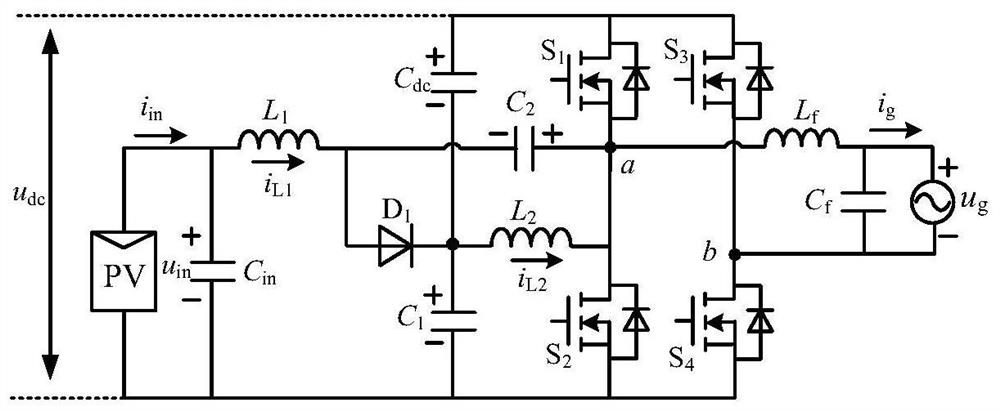
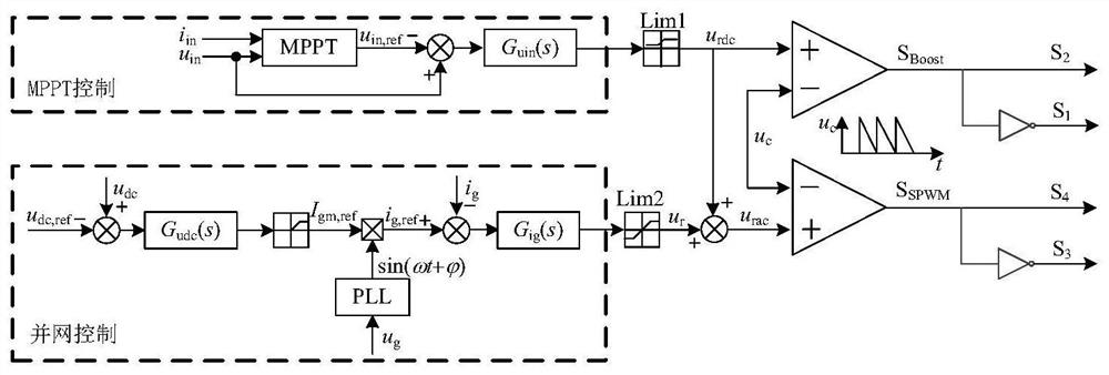
[0040] figure 2 A schematic circuit structure diagram of a single-phase high-gain photovoltaic grid-connected inverter with continuous input current according to an embodiment of the present application is shown. As an exemplary and non-limiting embodiment, the single-phase high-gain inverter includes a boost circuit, a full-bridge inverter circuit, and a filter circuit. The input end of the single-phase high-gain inverter is connected to th...


PUM


Abstract

The invention discloses a single-phase high-gain photovoltaic grid-connected inverter with continuous input current and a control method. The inverter includes a boost circuit and a full-bridge inverter circuit. The boost circuit includes a first boost inductor L 1 , the second boost inductor L 2 , the first boost capacitor C 1 , the second boost capacitor C 2 and the first boost diode D 1 . Inductance L 1 One end of the diode D 1 The anode, capacitor C 2 connected to the cathode of the diode D 1 The cathode and capacitance C 1 positive pole, inductance L 2 connected at one end. The full-bridge inverter circuit includes a switch tube S 1 ‑S 4 , switch tube S 1 and S 2 connected in series to form the first bridge arm circuit, the switch tube S 3 and S 4 The second bridge arm circuit is formed in series, and the two bridge arm circuits are connected in parallel. The present invention realizes the high-gain step-up inverter under the condition of low duty ratio, and has the advantages of continuous input current, adapting to wide-ranging input voltage changes, high conversion efficiency, low capacitor voltage stress, simple structure, and low cost. It is especially suitable for small and medium power distributed photovoltaic grid-connected power generation systems.

Description

technical field [0001] The present application relates to the technical field of inverter topology and control, in particular to a single-phase high-gain photovoltaic grid-connected inverter with continuous input current and a control method. Background technique [0002] In order to reduce the proportion of traditional fossil energy in the energy consumption structure and improve environmental pollution, the renewable energy distributed power generation system has been vigorously developed in various countries in recent years. In these power systems, the input side is usually a photovoltaic cell, a fuel cell or a storage battery, and its output voltage is low and has a large fluctuation range. In order to meet the voltage requirements of the power grid or AC load equipment, the above-mentioned systems generally adopt a two-stage structure of a DC / DC boost converter cascaded with a voltage source full-bridge inverter. This scheme can better adapt to the wide variation range...

Claims


Application Information

Patent Timeline
Patent Type & Authority Patents(China)
IPC IPC(8): H02M7/5387H02J3/38
CPCH02M7/53871H02M1/0009Y02E10/56
Inventor 秦岭周磊段冰莹田民沈家鹏高娟尹铭
Owner NANTONG UNIVERSITY
Learn More