Operation puncture positioner of laparoscope ultrasonic probe
A laparoscopic ultrasound and locator technology, applied in stereotaxic surgical instruments, surgical instrument parts, surgery, etc., can solve the problem of reducing the quality and efficiency of positioning punctures, not being able to provide solid support for the body, and increasing the workload of surgical personnel To improve the quality of positioning puncture, reduce the workload, and avoid the exposure of electrodes
- Summary
- Abstract
- Description
- Claims
- Application Information
AI Technical Summary
Problems solved by technology
Method used
Image

Examples
Embodiment 1
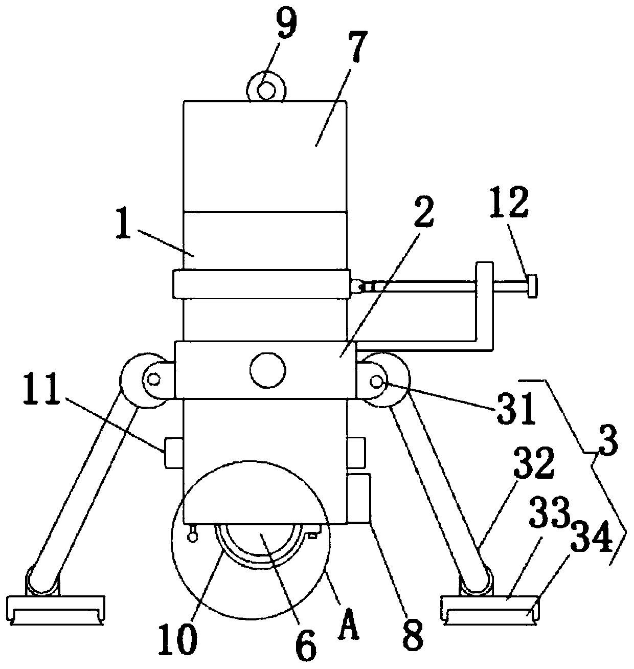
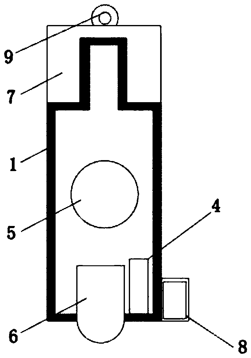
[0025]Embodiment 1: A puncture positioner for laparoscopic ultrasound probe surgery, including a body shell 1, a normally closed reed switch 4, a button battery 5 and a laser head 6, the rear end of the body shell 1 is a threaded column structure, and the device The rear end threaded column of the body shell 1 is threadedly connected with the cover base 7, the button battery 5 is arranged at the inner center of the body shell 1, the laser head 6 is set in the front opening of the body shell 1, and the magnet 8 is set in the body The front end of the shell 1, the normally closed reed switch 4 is arranged inside the front end of the body shell 1, and corresponds to the lateral position of the magnet 8, the terminal of the normally closed reed switch 4 is connected to the positive pole of the button battery 5 through a wire, The negative pole of the button battery 5 is connected to the terminal of the laser head 6 through a wire, and the laser head 6 is connected to the normally c...
Embodiment 2
[0028] The difference between this embodiment and Embodiment 1 is:
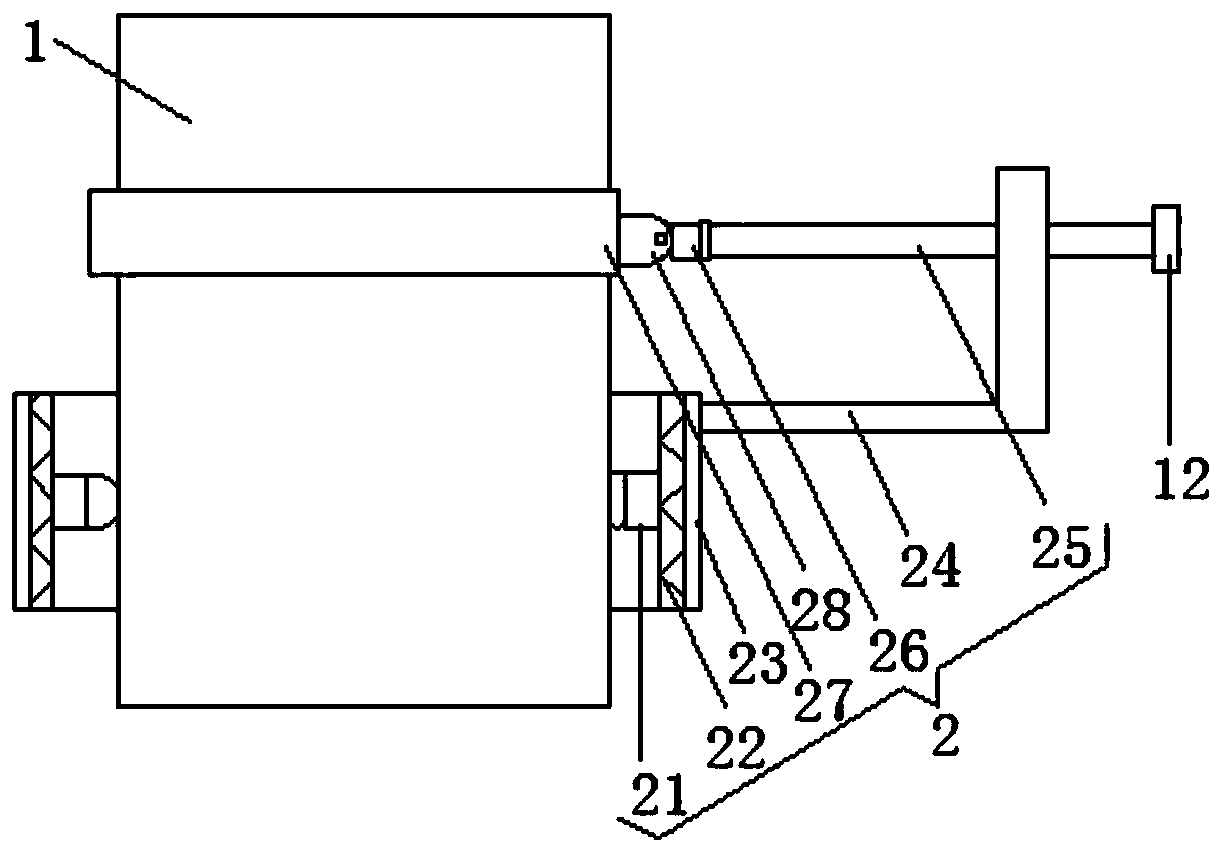
[0029] In this embodiment, the positioning angle adjustment mechanism 2 includes a universal ball joint 21, an adjustment bearing 22, a ring plate 23, an L-shaped support plate 24, an adjustment thread column 25, an adjustment round table 26, a driven bearing 27 and a U-shaped adjustment plate 28. The universal ball joint 21 is symmetrically arranged on the inner wall of the inner ring of the adjustment bearing 22, the rotating ball of the universal ball joint 21 is fixedly connected with the middle part of the outer surface of the body shell 1, and the ring plate 23 is correspondingly arranged on the inner wall of the adjustment bearing 22 On the outer wall of the outer ring, the L-shaped support plate 24 is arranged on the outer arc wall of the circular ring plate 23, and the adjusting thread column 25 is screwed to the vertical plate body of the L-shaped support plate 24, and the outer end surface of the ad...
Embodiment 3
[0034] The difference between this embodiment and Embodiment 1 is:
[0035] In this embodiment, the lifting mechanism 9 includes a printing groove 91, a folding handle 92 and a lifting introduction groove 93. The printing groove 91 is arranged on the rear wall of the cover base 7, and the folding handle 92 is correspondingly arranged inside the printing groove 91. The pull-in groove 93 is arranged on the rear wall of the cover base 7 and is arranged corresponding to the printing groove 91 .
[0036] Specifically, it is set up in this way, because the folding handle 92 is correspondingly arranged in the inside of the printing groove 91, and the lifting guide groove 93 is correspondingly arranged with the printing groove 91, and the personnel folds the folding handle 92 in the printing groove 91 by lifting the introducing groove 93 to carry The hanger body is convenient to carry and store. Since the folding handle 92 is correspondingly arranged inside the printing groove 91, it ...
PUM
 Abstract
Description
Claims
Application Information
 - R&D Engineer
- R&D Manager
- IP Professional
- Industry Leading Data Capabilities
- Powerful AI technology
- Patent DNA Extraction
Browse by: Latest US Patents, China's latest patents, Technical Efficacy Thesaurus, Application Domain, Technology Topic.
© 2024 PatSnap. All rights reserved.Legal|Privacy policy|Modern Slavery Act Transparency Statement|Sitemap