
Gantry type three-axis welding device capable of automatically identifying weld joint track and welding method of gantry type three-axis welding device

An automatic identification and welding device technology, applied in auxiliary devices, welding equipment, auxiliary welding equipment, etc., can solve the problems of low welding accuracy, difficulty in further improving welding efficiency, and workpiece installation errors.

Active Publication Date: 2020-07-07
JILIN UNIV +1
View PDF8 Cites 4 Cited by
  • Summary
  • Abstract
  • Description
  • Claims
  • Application Information

AI Technical Summary

Problems solved by technology

However, most of the current welding robots are manual teaching, that is, for each type of welding seam, the corresponding welding program must be edited before welding, which seriously hinders the improvement of welding robot welding efficiency:
[0003] (1) Welding robots based on manual teaching have poor adaptability to welding of different shapes of welds. When single-batch welding production or changing the shape of welds, especially outdoor robot welding, its inflexibility is highlighted
[0004] (2) Welding robots based on manual teaching will significantly increase the preparation time before welding and reduce welding efficiency, especially for long straight line welds and curved welds. Due to pre-weld programming, pre-weld workpiece installation and positioning, manual teaching before welding Increase the pre-weld preparation time, even make the pre-weld preparation time far exceed the actual welding time
[0005] (3) The welding robot based on manual teaching has poor welding accuracy. Due to the installation error of the workpiece before welding (the centerline curve of the weld seam is not parallel to the running route of the welding torch manually taught), the movement error of the welding torch, and the thermal deformation of the workpiece during the welding process will cause During the welding process, there is a deviation between the welding torch and the center of the weld seam, and the welding accuracy is relatively low
[0010] 1) This technology is more suitable for short welds and welds with large gaps (including plane straight line welds and plane curve welds). For long welds, welds with height difference and small welding distance, this technology cannot Accurately fitting the entire weld centerline coordinate curve is no longer applicable
[0011] 2) Even if this technology accurately fits the coordinate curve of the centerline of the entire weld seam through the CCD camera before welding, and delegates it to the controller to control the movement of the welding torch for welding, it cannot perceive the welding torch and welding caused by the thermal deformation of the workpiece during the welding process. Seam center deviation, the welding accuracy is not high
[0012] 3) Since a fixed CCD camera is used to take pictures of the entire weld seam before welding, the coordinates of the center point of the weld seam are positioned to fit the coordinate curve of the center line of the entire weld seam, so the requirements for the surrounding lighting environment are relatively strict when taking pictures, and the common welding environment is difficult. meet its requirements
[0016] However, this technology also has the following defects: when a small batch or a single weldment is produced, this welding technology cannot avoid the influence of long preparation time before welding brought about by tedious manual teaching, and its welding efficiency is difficult to be further improved in this respect

Method used


Image

  • Gantry type three-axis welding device capable of automatically identifying weld joint track and welding method of gantry type three-axis welding device
  • Gantry type three-axis welding device capable of automatically identifying weld joint track and welding method of gantry type three-axis welding device
  • Gantry type three-axis welding device capable of automatically identifying weld joint track and welding method of gantry type three-axis welding device

Examples


Embodiment Construction

[0096] The detailed content of the present invention and its specific implementation will be further described below in conjunction with the accompanying drawings.

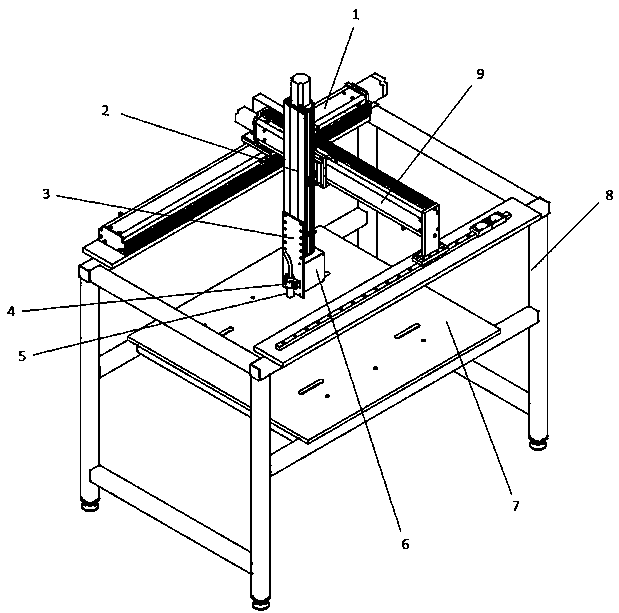
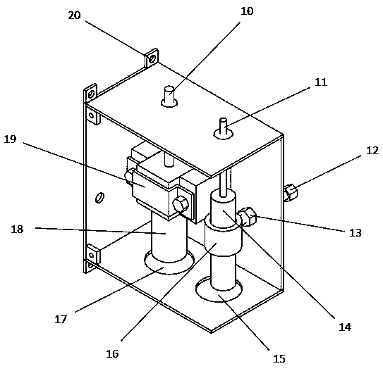
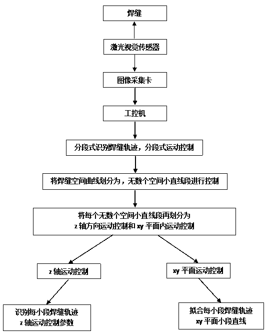
[0097] see Figure 1 to Figure 5 , the gantry-type three-axis welding device and welding method for automatic identification of welding seam track of the present invention, including industrial computer, gantry-type three-axis welding platform, laser vision sensor, image acquisition card, welding torch, welding machine, control cabinet; the invention provides A method for automatic identification of weld trajectory, under the moving relative coordinate system, fits the weld trajectory in segments; the pixel coordinates of the center points of each groove in the latter segment of the weld trajectory acquired by the laser vision sensor are compared with the previous segment , correct the fitting coordinate curve of the previous segment of the weld trajectory, and use it as the fitting coordinate curve of the subsequ...


PUM


Abstract

The invention relates to a gantry type three-axis welding device capable of automatically identifying a weld joint track and a welding method of the gantry type three-axis welding device, and belongsto the field of welding automation. The device comprises a gantry type three-axis welding platform, a laser vision sensor, an image acquisition card, a welding gun, a welding machine and a control cabinet; the gantry type three-axis welding platform is composed of a rigid body support, a welding platform operation area and a gantry type three-axis combined module and is provided with an absolute coordinate system o-xyz; the gantry type three-axis combined module is divided into an x-main axis module comprising an x-axis auxiliary guide rail, a y-axis module and a z-axis module; and the weldingplatform operation area is fixed in the middle of the rigid support, the x-main axis module and the x-axis auxiliary guide rail are fixed to the upper portion of the rigid support, the two ends of the y-axis module are connected to the x-main axis module and the x-axis auxiliary guide rail in a sliding mode, and the z-axis module is connected to the y-axis module in a sliding mode. The device hasthe advantages that the weld joint track is automatically identified in real time, the welding gun is automatically controlled to move, manual teaching is removed, the flexibility of the welding device is improved and the welding efficiency is improved.

Description

technical field [0001] The invention belongs to the field of welding automation, and in particular relates to automatic identification technology of welding trajectory, in particular to identification technology of gas shielded welding trajectory, especially a gantry-type three-axis welding device and welding method for automatic identification of welding seam trajectory. Background technique [0002] In the field of welding, compared with manual welding, welding automation technology has significantly increased welding speed, welding quality, welding accuracy and stability, and is increasingly favored by welding workers. However, most of the current welding robots are manual teaching, that is, for each type of welding seam, the corresponding welding program must be edited before welding, which seriously hinders the improvement of welding robot welding efficiency: [0003] (1) Welding robots based on manual teaching have poor adaptability to welding of different shapes of we...

Claims


Application Information

Patent Timeline
IPC IPC(8): B23K37/02B23K37/04B23K37/00
CPCB23K37/0252B23K37/0461B23K37/00Y02P70/10
Inventor 赵小辉王浩蔡宇杨彬
Owner JILIN UNIV
Learn More