Technological method of removing hydrogen chloride through powder injection of blast furnace gas pipeline and device of removing hydrogen chloride through powder injection of blast furnace gas pipeline

A kind of blast furnace gas, technology of process method

Active Publication Date: 2020-07-07
BEIJING PEKING UNIV PIONEER TECH
View PDF13 Cites 5 Cited by
  • Summary
  • Abstract
  • Description
  • Claims
  • Application Information

AI Technical Summary

Problems solved by technology

[0006] Most of the existing blast furnace gas fixed-bed dechlorination technologies have the following problems: 1. The on-site blast furnace gas purification equipment is compact, and there is no extra space on site to install additional dry-type acid removal adsorption towers; 2. Several types of acid removal adsorption towers are put into use. 3. There will be a lot of dust at the outlet of the dechlorination tower, and a filter device must be added; 4. The dechlorination agent is consumable, and it must be replaced after it penetrates. The dechlorination tower At least two units must be installed to ensure continuous production. Disassembling and assembling the dechlorination agent consumes manpower and material resources, which greatly increases the operation and maintenance cost of the device; secondary pollution to the environment

Method used


Image

  • Technological method of removing hydrogen chloride through powder injection of blast furnace gas pipeline and device of removing hydrogen chloride through powder injection of blast furnace gas pipeline
  • Technological method of removing hydrogen chloride through powder injection of blast furnace gas pipeline and device of removing hydrogen chloride through powder injection of blast furnace gas pipeline

Examples


Embodiment 1

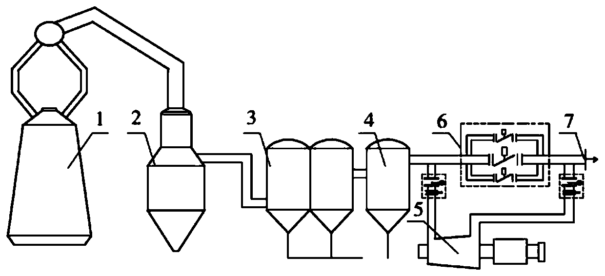
[0039] The condition of the blast furnace gas in the outlet pipeline of the coarse dust collector 2 is: the flow rate is 200,000 / Nm 3 / h, the pressure is about 0.2MPa, the temperature is about 150℃, the line speed is about 20m / s, and the dust content is 10g / m 3 , water content 52g / Nm 3 About, containing HCl 98mg / m 3 .

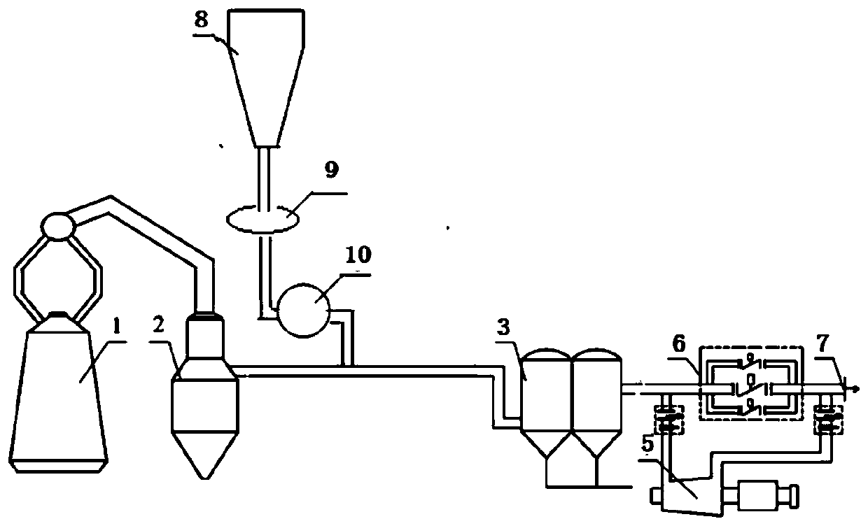
[0040] The larger particle dechlorination agent loaded in the hopper 8 of the dechlorination agent bag filter is ground into a powder below 300 mesh (50um) by the mill 9, and then the fan 10 draws and transports the dechlorination agent and sprays it. into the pipeline. The sprayed powder dechlorination agent is 100kg / h, and the powder content in the gas is 0.5g / m 3 . The dechlorination agent is activated in the pipeline, and the specific surface area increases rapidly. The powder particles are suspended in the air flow, and fully and evenly contact with the blast furnace gas for 1 to 2 seconds. A chemical reaction occurs, and the HCl in the blast furnace ...

Embodiment 2

[0043] The condition of the blast furnace gas in the outlet pipeline of the coarse dust collector 2 is: the gas flow rate is 200,000 / Nm 3 / h, the pressure is about 0.2MPa, the temperature is about 150℃, the line speed is about 20m / s, and the dust content is 10g / m 3 , water content 52g / Nm 3 About, containing HCl 103mg / m 3 .

[0044] The larger particle dechlorination agent loaded in the hopper 8 of the dechlorination agent bag filter is ground into a powder below 300 mesh (50um) by the mill 9, and then the fan 10 draws and transports the dechlorination agent and sprays it. into the pipeline. The sprayed powder dechlorination agent is 60kg / h, and the powder content in the gas is 0.3g / m 3 . The dechlorination agent is activated in the pipeline, and the specific surface area increases rapidly. The powder particles are suspended in the air flow, and fully and evenly contact with the blast furnace gas for 1 to 2 seconds. A chemical reaction occurs, and the HCl in the blast furn...

Embodiment 3

[0047] The condition of the blast furnace gas in the outlet pipeline of the coarse dust collector 2 is: the gas flow rate is 200,000 / Nm 3 / h, the pressure is about 0.2MPa, the temperature is about 150℃, the line speed is about 20m / s, and the dust content is 10g / m 3 , water content 52g / Nm 3 About, containing HCl 110mg / m 3 .

[0048] The larger particle dechlorination agent loaded in the hopper 8 of the dechlorination agent bag filter is ground into a powder below 300 mesh (50um) by the mill 9, and then the fan 10 draws and transports the dechlorination agent and sprays it. into the pipeline. The sprayed powder dechlorination agent is 50kg / h, and the powder content in the gas is 0.25g / m 3 . The dechlorination agent is activated in the pipeline, and the specific surface area increases rapidly. The powder particles are suspended in the air flow, and fully and evenly contact with the blast furnace gas for 1 to 2 seconds. A chemical reaction occurs, and the HCl in the blast fur...


PUM


Abstract

The invention discloses a technological method of removing hydrogen chloride through powder injection of a blast furnace gas pipeline and a device of removing hydrogen chloride through powder injection of the blast furnace gas pipeline. The device utilizing the technology of adopting blast furnace gas pipeline powder injection to remove hydrogen chloride adopts the dry type blast furnace gas injecting dechloridation technology to remove hydrogen chloride; a dechlorination agent bag-type dust collector hopper, a pulverizer and a draught fan are sequentially mounted on a pipeline behind a dry process coarse dust remover and in front of the bag-type dust collector of the existing device; and the condition of blast furnace gas in an outlet pipeline of the dry process coarse dust remover is set; through grinding, the dechlorination agent obtains a larger specific surface area, and the ground dechlorination agent is directly injected in the blast furnace gas pipeline for dechloridation reaction through the powder injection manner. With adoption of the technical scheme, the one-time investment is less, the occupied area is small, and the system is simple in operation and convenient to maintain. The technology can effectively improve the contact uniformity and sufficiency of the dechlorination agent and blast furnace gas, improves the dry process dechlorination effect, is low in heat loss of blast furnace gas and does not affect later application of TRT.

Description

technical field [0001] The invention relates to the technical field of blast furnace gas purification, in particular to a process and a device for removing hydrogen chloride by powder spraying in a blast furnace gas pipeline. Background technique [0002] In recent years, domestic iron and steel enterprises have generally adopted dry-type bag filter technology for blast furnace gas, which has brought great economic and social benefits. However, with the continuous accumulation of production experience, it has been found that when the blast furnace gas adopts full dry bag dust removal, because the gas contains ammonia, chlorine, sulfur and other impurities, the blast furnace gas residual pressure turbine power generation unit (Blast Furnace Top Gas Recovery Turbine Unit) , hereinafter referred to as TRT), pipeline system and auxiliary equipment, there are a lot of salt accumulation and corrosion problems, which have brought huge economic losses to the enterprise, and also gre...

Claims


Application Information

Patent Timeline
IPC IPC(8): C21B5/06C21B7/22
CPCC21B5/06C21B7/22Y02P10/25
Inventor 梁曙光郭迎秋
Owner BEIJING PEKING UNIV PIONEER TECH
Why Eureka
Try Eureka