
Red phosphorescent host compound and organic light emitting device using same

A red phosphorescence and compound technology, applied in the field of soluble phosphorescence host compounds and OLED devices, can solve problems such as lack of materials, and achieve the effects of easy availability of raw materials, reduction of vibration energy loss, and high-efficiency luminescence performance

Pending Publication Date: 2020-07-10
ZHEJIANG HUADISPLAY OPTOELECTRONICS CO LTD
View PDF4 Cites 1 Cited by
  • Summary
  • Abstract
  • Description
  • Claims
  • Application Information

AI Technical Summary

Problems solved by technology

Currently, host materials with both high triplet energy levels and good hole mobility are still lacking.

Method used


Image

  • Red phosphorescent host compound and organic light emitting device using same
  • Red phosphorescent host compound and organic light emitting device using same
  • Red phosphorescent host compound and organic light emitting device using same

Examples


Embodiment 1

[0034] Embodiment 1: the synthesis of compound 1

[0035] Synthesis of Intermediate Sub-1

[0036]

[0037] In the 500mL reaction flask, add intermediate phenylboronic acid (7.49g, 61.4mmol), 2,4-dibromothiazole (17.68g, 61.4mmol), tetrakis (triphenylphosphine) palladium (5mol%), K2CO3 (17.0g , 122.8mmol), 1,4-dioxane (200mL) and water (50mL). The temperature of the reaction system was raised to 80° C., and reacted for 12 hours under the protection of nitrogen. After the reaction was completed, the reaction solution was cooled to room temperature, and extracted with o-dichlorobenzene and water. The organic layer was dried over anhydrous magnesium sulfate, concentrated, and recrystallized to obtain the crude product through a silica gel column to obtain intermediate Sub-1 (13.13 g, yield 75%) LC-MS: M / Z 283.99 (M+H)+

[0038] Synthesis of compound 1

[0039]

[0040] In a 250mL three-necked flask, add intermediate 5,10-dihydrophenazine (1.82g, 10.0mmol), intermediate ...

Embodiment 2

[0041]Embodiment 2: the synthesis of compound 14

[0042] Synthesis of Intermediate Sub-2

[0043]

[0044] Add intermediate 2,4-dibromobenzo[4,5]thieno[3,2-d]pyrimidine (3.85g, 11.2mmol) and intermediate carbazole (3.0g, 12.3mmol) in a 250mL three-necked flask , tris(dibenzylideneacetone)dipalladium (4 mol%), tri-tert-butylphosphine (8 mol%), potassium tert-butoxide (3.8 g, 33.6 mmol) and o-xylene (80 mL). The temperature of the reaction system was raised to 120° C. and reacted for 12 hours under the protection of nitrogen. After the reaction was completed, the reaction solution was cooled to room temperature, and extracted with o-dichlorobenzene and water. The organic layer was dried over anhydrous magnesium sulfate, concentrated, and the crude product obtained by recrystallization was passed through a silica gel column to obtain Sub-2 (3.86 g, yield 80%). LC-MS: M / Z 430.32 (M+H)+.

[0045] Synthesis of Compound 14

[0046]

[0047] Compound 14 was synthesized wit...

Embodiment 3

[0048] Embodiment 3: the synthesis of compound 22

[0049]

[0050] Compound 22 was synthesized with reference to the method of Example 2, and other steps were referred to the synthesis of Example 2 to obtain Compound 22 (6.55 g, yield 55%). LC-MS: M / Z 1062.30 (M+H)+.


PUM


Abstract

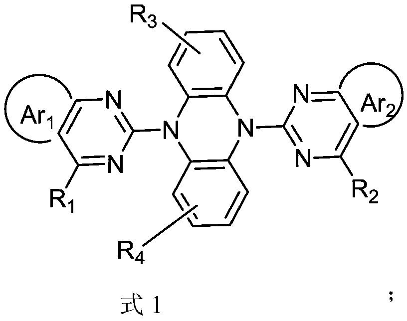
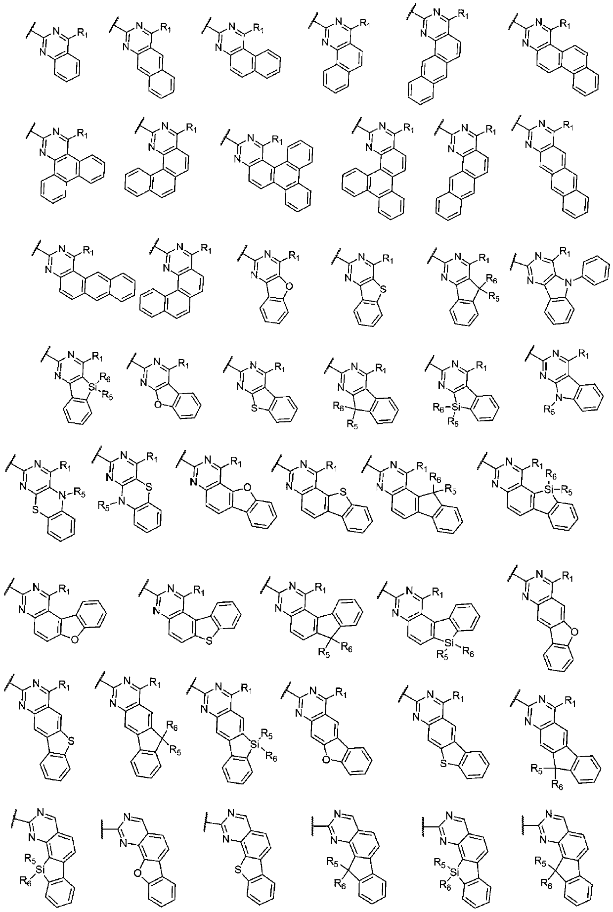
The present invention relates to a red phosphorescent host compound and an organic light emitting device using the same, and more specifically, to a soluble phosphorescent host compound having excellent color purity and high luminance and light-emitting efficiency, and an OLED device using the same. The structure of the red phosphorescent host compound provided by the invention is shown as a formula 1, wherein in the structural formula, Ar1 and Ar2 are independently selected from substituted or unsubstituted C6-C30 aryl and substituted or unsubstituted C2-C30 heteroaryl respectively, R1 to R4are independently selected from a substituted or unsubstituted alkyl group, a substituted or unsubstituted C6-C60 aryl group, a substituted or unsubstituted C3-C60 nitrogen-containing heteroaryl group, or a combination of the substituted or unsubstituted alkyl group, the substituted or unsubstituted C6-C60 aryl group and the substituted or unsubstituted C3-C60 nitrogen-containing heteroaryl group.

Description

technical field [0001] The present invention relates to a red phosphorescent host compound and an organic light-emitting device using the compound, more specifically, to a soluble phosphorescent host compound with excellent color purity, high brightness and luminous efficiency and an OLED device using the compound. Background technique [0002] With the development of multimedia technology and the improvement of informatization requirements, the performance requirements of panel displays are getting higher and higher. Among them, OLED has a series of advantages such as self-luminescence, low-voltage DC drive, full curing, wide viewing angle, and rich colors. It has attracted widespread attention for its potential application in the new generation of display and lighting technologies, and its application prospects are very broad. Organic electroluminescent devices are spontaneous light-emitting devices. The mechanism of OLED light emission is that under the action of an exter...

Claims


Application Information

Patent Timeline
Patent Type & Authority Applications(China)
IPC IPC(8): C07D403/14C07D519/00C07F7/08C09K11/06H01L51/54
CPCC07D403/14C07D519/00C07F7/0816C09K11/06C09K2211/1044C09K2211/1029C09K2211/1048C09K2211/1051C09K2211/1055C09K2211/1059C09K2211/1066C09K2211/1062C09K2211/1011C09K2211/1007H10K85/626H10K85/615H10K85/657H10K85/40H10K85/6572
Inventor 高春吉汪华月钱烨
Owner ZHEJIANG HUADISPLAY OPTOELECTRONICS CO LTD
Learn More