Metal plate surface treatment equipment
A surface treatment and metal plate technology, applied in metal material coating process, ion implantation plating, coating, etc., can solve the problems of lack of industrialized overall equipment, etc., and achieve the effect of compact structure, strong sealing and better effect
- Summary
- Abstract
- Description
- Claims
- Application Information
AI Technical Summary
Problems solved by technology
Method used
Image
Examples
Embodiment 1
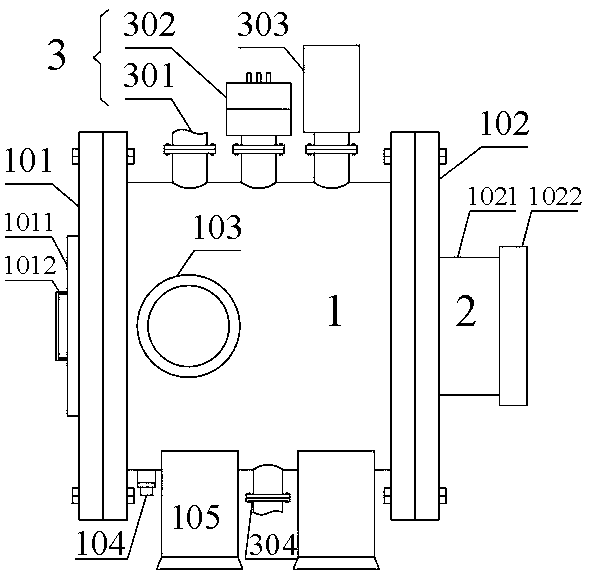
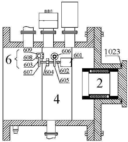
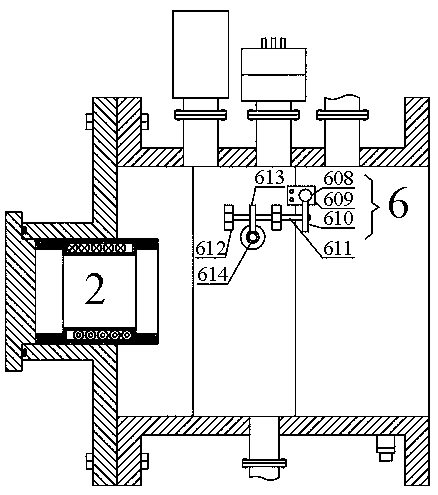
[0045] Such as figure 1 As shown, the metal plate surface treatment equipment includes a pot-shaped sealed chamber 1, an electric spray gun 2 installed on the right side of the sealed chamber 1 and used to excite electroplating particles, a vacuum device 3 connected to the inside of the sealed chamber 1, and installed in the sealed chamber 1 The internal operating device 4 , the carrier 5 arranged on the operating device 4 and used for fixing the metal parts 7 , and the driving device 6 for driving the operating device 4 to work. It should be noted that the running device 4 drives the metal piece 7 in the carrier 5 to move, so as to ensure that the outer surface of the metal piece 7 is fully exposed to the action area of the electrospray gun 2 to achieve a uniform alloy layer on the surface.
[0046] figure 1 Among them, the left side of the sealing chamber 1 is provided with a sealing cover 101 through a flange, and the right side of the sealing chamber 1 is provided with ...
Embodiment 2
[0051] Such as figure 2 , such as 3 and Figure 4 As shown, the electrospray gun 2 includes a gun body 201, a plasma device 202 and an electroplating plate 203, the gun body 201 is concentrically arranged in the installation cavity 1021, the plasma device 202 is installed on the end of the gun body 201 away from the sealed chamber 1, and the electroplating plate 203 is installed on the The gun body 201 is close to the other end of the sealed chamber 1 .
[0052] It should be noted that after the plasma device 202 and the electroplating plate 203 are energized, electrons are generated, and after the electrons bombard the electroplating plate 203, high-energy electroplating ions are excited, and the high-energy electroplating ions act on the surface of the metal piece 7 to form an alloy coating.
[0053] Concretely, in order to further enhance the effectiveness of electroplating ions, a solenoid 204 for generating an accelerating magnetic field is also provided in the middle o...
Embodiment 3
[0055] Such as Figure 5 , Image 6 with Figure 7 As shown, the running device 4 includes a bearing plate 401 , a sprocket device 402 , a connecting piece 403 and a connecting shaft 404 . In the figure, two groups of bearing plates 401 are symmetrically fixed in the inner cavity of the sealed chamber 1, each group of bearing plates 401 is equipped with a sprocket device 402, and the same positions of the two groups of sprocket devices 402 are respectively installed with connectors 403, The two sets of connecting pieces 403 are connected to both sides of the carrier 5 through connecting shafts 404 .
[0056] Specifically, the sprocket device 402 is divided into a first sprocket set 4021 and a second sprocket set 4022, and the first sprocket set 4021 and the second sprocket set 4022 both include upper and lower sprockets 4023 and corresponding chains 4024, The sprocket 4023 is mounted on a sprocket bearing 4026 on the bearing plate 401 via a sprocket shaft 4025 .
[0057] I...
PUM
 Abstract
Description
Claims
Application Information
 - R&D
- Intellectual Property
- Life Sciences
- Materials
- Tech Scout
- Unparalleled Data Quality
- Higher Quality Content
- 60% Fewer Hallucinations
Browse by: Latest US Patents, China's latest patents, Technical Efficacy Thesaurus, Application Domain, Technology Topic, Popular Technical Reports.
© 2025 PatSnap. All rights reserved.Legal|Privacy policy|Modern Slavery Act Transparency Statement|Sitemap|About US| Contact US: help@patsnap.com


