Equipment and method for continuous takt type vacuum heat treatment of workpieces

A vacuum heat treatment and heat treatment chamber technology, applied in heat treatment equipment, heat treatment furnaces, quenching devices, etc., can solve the problems of difficult mass continuous production, high energy consumption, long production cycle, etc., to achieve high production efficiency, low energy consumption, Stable quality effect

Pending Publication Date: 2020-07-17
兰州广合新材料科技有限公司
View PDF0 Cites 2 Cited by
  • Summary
  • Abstract
  • Description
  • Claims
  • Application Information

AI Technical Summary

Problems solved by technology

[0003] The disadvantage of vacuum heat treatment technology is that in most cases, the workpiece can only be clamped and placed in the vacuum furnace. After closing the vacuum furnace door, the vacuum is first pumped to a higher vacuum degree, and then the heating system is turned on to heat the workpiece to the process temperature and keep it constant. time, then cool the workpiece at the cooling rate required by the process, and finally deflate the vacuum chamber and open the furnace door to take out the workpiece
Due to the repeated processes of closing the door, vacuuming, venting, opening the door, heating and cooling, etc., resulting in a long production cycle and high energy consumption, conventional vacuum heat treatment technology is difficult to apply to industrialized mass production.

Method used


Image

  • Equipment and method for continuous takt type vacuum heat treatment of workpieces
  • Equipment and method for continuous takt type vacuum heat treatment of workpieces

Examples


Embodiment 1

[0033] High speed steel turning blade (material: SKH-51) continuous vacuum quenching and tempering

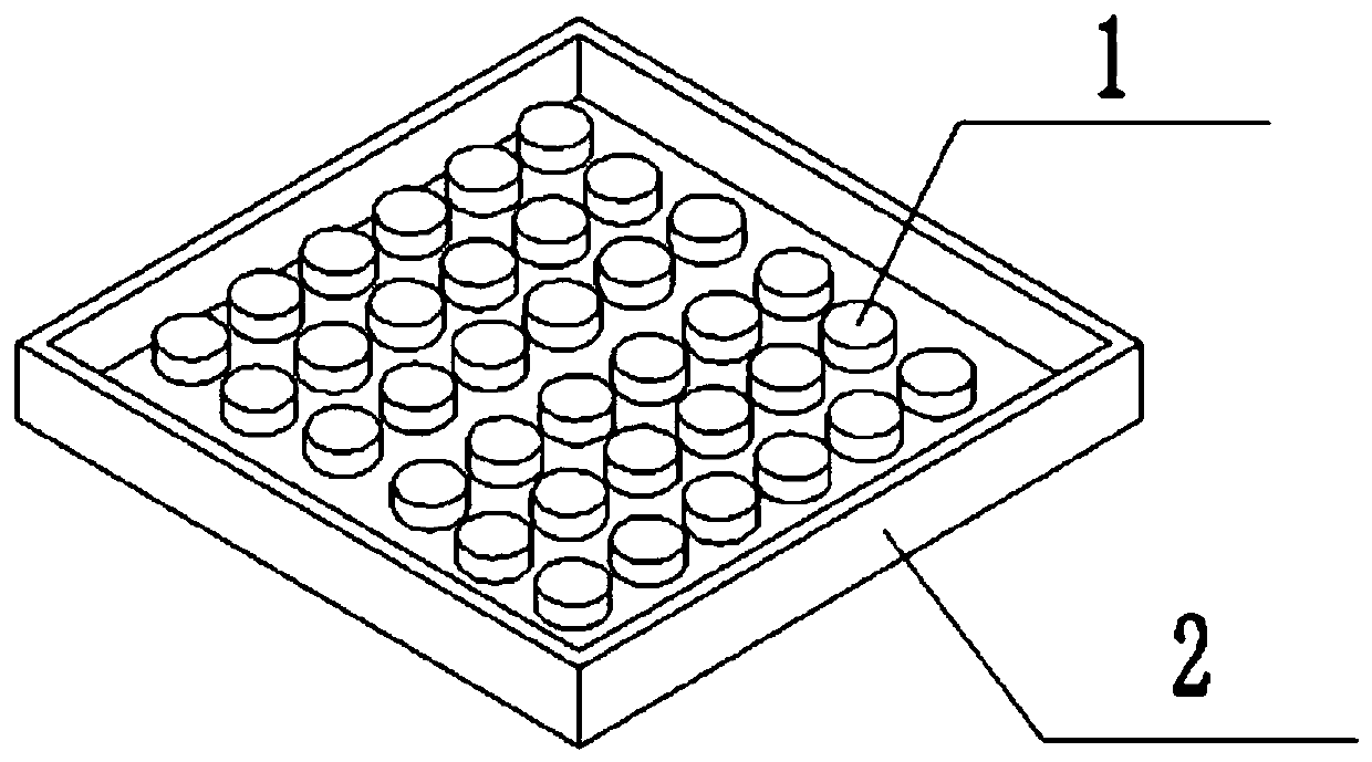
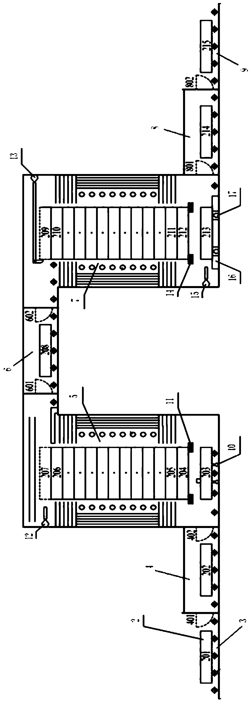
[0034] (1) No-load installation of workpiece tray 2: Open flap valve 1 401, flap valve 2 402, flap valve 3 601 and flap valve 4 602, open the transmission mechanism, and send multiple empty workpiece trays 2 continuously Form 204 to 206 lamination layers in the high-temperature vacuum heat treatment chamber 5, and send them into the lamination layers forming 210-212 in the low-temperature vacuum heat treatment chamber 7; close flap valve one 401, flap valve two 402, flap valve three 601, Flap valve four 602, flap valve five 801 and flap valve six 802;

[0035] (2) Open the vacuum acquisition system; open the vacuum valves of the entrance transition chamber 4, high temperature vacuum heat treatment chamber 5, gas quenching chamber 6, low temperature vacuum heat treatment chamber 7 and outlet transition chamber 8, so that the vacuum degree is maintained at 5X10 -2 Pa;

[0036] ...

Embodiment 2

[0050] Solid Solution and Aging of Beryllium Bronze High Conductivity Contact Electrode

[0051] (1) No-load installation of workpiece tray 2: Open flap valve 1 401, flap valve 2 402, flap valve 3 601 and flap valve 4 602, open the transmission mechanism, and send multiple empty workpiece trays 2 continuously Form 204 to 206 lamination layers in the high-temperature vacuum heat treatment chamber 5, and send them into the lamination layers forming 210-212 in the low-temperature vacuum heat treatment chamber 7; close flap valve one 401, flap valve two 402, flap valve three 601, Flap valve four 602, flap valve five 801 and flap valve six 802;

[0052] (2) Open the vacuum acquisition system; open the vacuum valves of the entrance transition chamber 4, high temperature vacuum heat treatment chamber 5, gas quenching chamber 6, low temperature vacuum heat treatment chamber 7 and outlet transition chamber 8, so that the vacuum degree is maintained at 5X10 -2 Pa;

[0053] (3) Heating...

Embodiment 3

[0067] Preparation of 6.5wt.% Si high-silicon steel sheet by high-temperature diffusion and Si infiltration on low-silicon steel sheet coated with Si-rich film and low-temperature annealing treatment

[0068] (1) No-load installation of workpiece tray 2: Open flap valve 1 401, flap valve 2 402, flap valve 3 601 and flap valve 4 602, open the transmission mechanism, and send multiple empty workpiece trays 2 continuously Form 204 to 206 lamination layers in the high-temperature vacuum heat treatment chamber 5, and send them into the lamination layers forming 210-212 in the low-temperature vacuum heat treatment chamber 7; close flap valve one 401, flap valve two 402, flap valve three 601, Flap valve four 602, flap valve five 801 and flap valve six 802;

[0069] (2) Open the vacuum obtaining system 18; open the vacuum valves of the entrance transition chamber 4, high temperature vacuum heat treatment chamber 5, gas quenching chamber 6, low temperature vacuum heat treatment chamber...


PUM

PropertyMeasurementUnit
hardnessaaaaaaaaaa
thicknessaaaaaaaaaa

Abstract

The invention relates to equipment and a method for continuous takt type vacuum heat treatment of workpieces. According to the technical scheme, the equipment includes a feeding platform, an inlet transition bin, a high-temperature vacuum heat treatment chamber, a gas quenching chamber, a low-temperature vacuum heat treatment chamber, a forced cooling platform, an outlet transition bin and a discharging table which are sequentially connected, and the feeding table, the inlet transition bin, the forced cooling platform, the outlet transition bin and the discharging table are in the same horizontal plane with the bottoms of the high-temperature vacuum heat treatment chamber and the low-temperature vacuum heat treatment chamber; the gas quenching chamber is in the same horizontal plane with the tops of the high-temperature vacuum heat treatment chamber and low-temperature vacuum heat treatment chamber; a vacuum acquisition system communicates with the inlet transition bin, the high temperature vacuum heat treatment chamber, the gas quenching chamber, the low temperature vacuum heat treatment chamber and the outlet transition bin; a transmission mechanism is used for transferring a workpiece tray for loading workpieces; and an automatic control system is used for controlling a working takt interval period. According to the equipment and method, industrial scale continuous vacuum heat treatment machining of batch workpieces is realized, and the equipment and method have the advantages of high production efficiency, stable quality, low energy consumption and the like.

Description

technical field [0001] The invention belongs to the field of metal material thermal processing technology and equipment, and in particular relates to equipment and a method for continuous beat vacuum heat treatment of workpieces. Background technique [0002] Vacuum heat treatment is a new heat treatment technology combining vacuum technology and heat treatment technology. Compared with conventional heat treatment, vacuum heat treatment can realize almost all heat treatment processes involved in conventional heat treatment, but the quality of heat treatment is greatly improved. At the same time of vacuum heat treatment, it can realize no oxidation, no decarburization, no carburization, can remove phosphorus chips on the surface of the workpiece, and has the functions of degreasing and degassing, so as to achieve the effect of surface brightening and purification. The current vacuum high-pressure air-cooling quenching technology not only greatly improves the vacuum air-cooli...

Claims


Application Information

Patent Timeline
Patent Type & Authority Applications(China)
IPC IPC(8): C21D1/773C21D9/22C21D1/62C21D9/46C21D1/26C23C10/08C22F1/08C22F1/02H01F41/02
CPCC21D1/26C21D1/62C21D1/773C21D9/0018C21D9/0025C21D9/0062C21D9/22C21D9/46C22F1/02C22F1/08C23C10/08H01F41/0253
Inventor 田世宇田广科
Owner 兰州广合新材料科技有限公司
Why Eureka
Try Eureka