Paper current collector, preparation method thereof, electrode and battery

A current collector, paper technology, applied in the direction of electrode carrier/current collector, secondary battery, battery electrode, etc., can solve the problems of reducing thickness, low safety performance and high density of lithium ion battery, and achieve good strength and waterproof performance. Effect

Inactive Publication Date: 2020-07-17
BATTERO TECH CORP LTD
View PDF8 Cites 2 Cited by
  • Summary
  • Abstract
  • Description
  • Claims
  • Application Information

AI Technical Summary

Problems solved by technology

[0002] At present, the current collectors of lithium-ion batteries generally use copper foil and aluminum foil. From the perspective of the current-carrying capacity requirements of the current collector during the charging and discharging current of lithium-ion batteries, although the thickness of copper and aluminum foil can meet the requirements, the current application is the most The thickness of the thinnest aluminum foil is 10μm, and the thickness of the thinnest copper foil is 6μm. It is mainly affected by the processing ability of the copper and aluminum foil itself and the difficulty of the manufacturing process of the pole piece. It is difficult to further reduce the thickness of pure copper foil and aluminum foil.
[0003] In addition, due to the high density of copper foil and aluminum foil, especially copper foil, its current collector accounts for about 8% of the weight of the battery, and the impact on the weight energy density of the battery cannot be ignored. Therefore, lithium-ion batteries made using traditional current collectors There is a problem of low security performance

Method used


Image

  • Paper current collector, preparation method thereof, electrode and battery
  • Paper current collector, preparation method thereof, electrode and battery

Examples


Embodiment 1

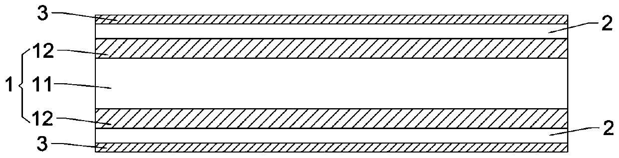
[0028] as attached figure 1 As shown, this embodiment provides a paper current collector, which includes a multilayer structural fiber layer 1, a metal coating 2 and a carbon base coating 3, and the multilayer structural fiber layer 1 includes at least one layer of nanocellulose base paper layer 11, both sides of the nanocellulose base paper layer 11 are provided with a composite paper coating 12; the side of the composite paper coating 12 away from the nanocellulose base paper layer 11 is provided with the metal coating 2. The side of the metal coating 2 away from the composite paper coating 12 is provided with the carbon base coating 3; the composite paper coating 12 includes nano-cellulose, inorganic fillers and nano-rubber additives. Wherein, the nano-cellulose is natural plant cellulose; the inorganic filler is calcium sulfate; the nano-rubber additive is styrene-butadiene latex; the carbon-based coating includes a carbon-based material and a polymer adhesive; the carbon-...

Embodiment 2

[0037] This embodiment provides a paper current collector, the structure of which differs from that of Embodiment 1 only in that the metal plating of the paper current collector is copper plating.

[0038] In addition, the difference between the preparation method of the paper current collector and Example 1 is that the preparation method is to vapor-deposit copper on the above-mentioned two-layer composite paper coating 12 by vacuum evaporation, which is far away from the nanocellulose base paper. On one side of the layer 11, two metal plating layers 2 each having a thickness of 1.25 μm were formed.

Embodiment 3

[0040] This embodiment provides a paper current collector, the structure of which differs from that of Embodiment 1 only in that: the nanocellulose is modified cellulose; the inorganic filler is calcium carbonate.

[0041] In addition, the difference between the preparation method of the paper-based current collector and Example 1 is that the preparation method is to transfer the aluminum-coated polyethylene terephthalate (Polyethylene Terephthalate, PET) The aluminum on the release film is transferred to the side of the above-mentioned two-layer composite paper coating 12 away from the nanocellulose base paper layer 11 to form two metal coatings 2 with a thickness of 1.25 μm.


PUM

PropertyMeasurementUnit
Thicknessaaaaaaaaaa
Thicknessaaaaaaaaaa
Thicknessaaaaaaaaaa

Abstract

The invention is applicable to the technical field of batteries, and provides a paper current collector, a preparation method thereof, an electrode and a battery. The paper current collector comprisesa multi-layer structure fiber layer, a metal plating layer and a carbon substrate coating. The multi-layer structure fiber layer comprises at least one nano cellulose raw paper layer, and the two sides of the nano cellulose raw paper layer are both provided with a composite paper coating; the metal plating layer is arranged on one side, far away from the nano cellulose base paper layer, of the composite paper coating; the carbon substrate coating is arranged on one side, far away from the composite paper coating, of the metal plating layer; the composite paper coating comprises nano cellulose, an inorganic filler and a nano rubber additive. The composite paper coating is arranged on the two sides of the nano cellulose raw paper layer so that the nano cellulose raw paper layer has good strength and waterproof performance. In addition, the lithium ion battery prepared from the paper current collector has relatively high weight energy density and relatively high safety performance.

Description

technical field [0001] The invention belongs to the technical field of batteries, and in particular relates to a paper current collector, a preparation method thereof, an electrode and a battery. Background technique [0002] At present, the current collectors of lithium-ion batteries generally use copper foil and aluminum foil. From the perspective of the current-carrying capacity requirements of the current collector during the charging and discharging current of lithium-ion batteries, although the thickness of copper and aluminum foil can meet the requirements, the current application is the most The thickness of the thinnest aluminum foil is 10μm, and the thickness of the thinnest copper foil is 6μm. It is mainly affected by the processing ability of the copper and aluminum foil itself and the difficulty of the manufacturing process of the pole piece. It is difficult to further reduce the thickness of pure copper foil and aluminum foil. [0003] In addition, due to the h...

Claims


Application Information

Patent Timeline
IPC IPC(8): H01M4/66H01M4/131H01M4/133H01M4/136H01M10/0525D21H19/38D21H19/52D21H19/58D21H19/64D21H19/82D21H19/84
CPCD21H19/38D21H19/52D21H19/58D21H19/64D21H19/82D21H19/84H01M4/131H01M4/133H01M4/136H01M4/661H01M4/663H01M4/667H01M10/0525Y02E60/10
Inventor 张五堂
Owner BATTERO TECH CORP LTD
Why Eureka
Try Eureka