A spiro compound and application, and organic electroluminescent device and electronic device using the same
A technology of spiro compounds and compounds, applied in the field of organic electroluminescent devices and electronic devices, can solve immature and huge problems, and achieve the effects of good film-forming morphology, large molecular weight, and large space volume
- Summary
- Abstract
- Description
- Claims
- Application Information
AI Technical Summary
Problems solved by technology
Method used
Image
Examples
Embodiment 1
[0264] Embodiment 1: red organic electroluminescent device
[0265] The anode was prepared by the following process: the thickness was The ITO substrate (manufactured by Corning) was cut into a size of 40mm×40mm×0.7mm, and it was prepared into an experimental substrate with cathode, anode and insulating layer patterns by photolithography process, using ultraviolet ozone and O 2 :N 2 Plasma surface treatment was performed to increase the work function of the anode (experimental substrate) and to remove scum.
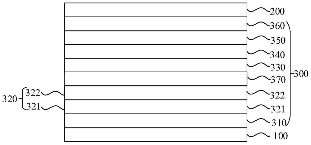
[0266] HAT-CN was vacuum evaporated on the experimental substrate (anode) to form a thickness of The hole injection layer (HIL), and compound 1 is vapor-deposited on the hole injection layer to form a thickness of The first hole transport layer (HTL-1).
[0267] TCTA is vacuum evaporated on the first hole transport layer to form a thickness of The second hole transport layer (HTL-2).
[0268] On the second hole transport layer, CBP is used as the host while dopi...
Embodiment 2- Embodiment 22
[0272] An organic electroluminescent device was fabricated by the same method as in Example 1, except that compounds shown in Table 16 below were used instead of Compound 1 when forming the first hole transport layer.
Embodiment 23
[0286] Example 23: Green organic electroluminescence device
[0287] The anode was prepared by the following process: the thickness was The ITO substrate (manufactured by Corning) was cut into a size of 40mm×40mm×0.7mm, and it was prepared into an experimental substrate with cathode, anode and insulating layer patterns by photolithography process, using ultraviolet ozone and O 2 :N 2 Plasma surface treatment was performed to increase the work function of the anode (experimental substrate) and to remove scum.
[0288] Vacuum evaporation of F4-TCNQ on the experimental substrate (anode) to form a thickness of The hole injection layer (HIL), and NPB is evaporated on the hole injection layer to form a thickness of The first hole transport layer (HTL-1).
[0289] Compound 15 is vacuum evaporated on the first hole transport layer to form a thickness of The second hole transport layer (HTL-2).
[0290] On the second hole transport layer, CBP: Ir(ppy) 3 Co-evaporated with a ...
PUM
 Abstract
Description
Claims
Application Information
 - R&D
- Intellectual Property
- Life Sciences
- Materials
- Tech Scout
- Unparalleled Data Quality
- Higher Quality Content
- 60% Fewer Hallucinations
Browse by: Latest US Patents, China's latest patents, Technical Efficacy Thesaurus, Application Domain, Technology Topic, Popular Technical Reports.
© 2025 PatSnap. All rights reserved.Legal|Privacy policy|Modern Slavery Act Transparency Statement|Sitemap|About US| Contact US: help@patsnap.com


