
Electroplating method, device and equipment and storage medium

A technology of electroplating tank and plating solution, which is applied in the direction of electrolysis process, electrolysis components, cells, etc., and can solve problems such as the decrease of the bonding force between the coating layer and the workpiece, the effect is not very ideal, the stability of the electroplating quality, and the difficulty in satisfying the electroplating of workpieces with high requirements.

Pending Publication Date: 2020-07-28
苏州融睿电子科技有限公司
View PDF0 Cites 0 Cited by
  • Summary
  • Abstract
  • Description
  • Claims
  • Application Information

AI Technical Summary

Problems solved by technology

[0004] However, if the existing electroplating process is used for direct electroplating, it is difficult for the electroplating solution to enter the hole due to the deep hole and blind hole structure, and electroplating assistance (such as exhaust, plating solution circulation, etc.) is required.
At present, there are some electroplating auxiliary methods, but the overall effect is not very ideal (it is difficult to guarantee the stability of electroplating quality by using a fixed auxiliary electroplating method for different workpieces, for example, there will be problems such as the decrease of the bonding force between the coating and the workpiece, and the uneven thickness of the coating. ), it is difficult to meet the requirements of electroplating for workpieces with high requirements

Method used


Image

  • Electroplating method, device and equipment and storage medium
  • Electroplating method, device and equipment and storage medium
  • Electroplating method, device and equipment and storage medium

Examples


Embodiment Construction

[0030] The technical solutions in the embodiments of the present application will be described below with reference to the drawings in the embodiments of the present application.

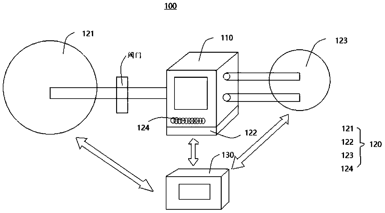
[0031] see figure 1 , figure 1 It is a schematic diagram of an electroplating equipment 100 provided in the embodiment of the present application.

[0032] In this embodiment, the electroplating equipment 100 can include an electroplating tank 110 and an auxiliary device 120, wherein the electroplating tank 110 can be used to accommodate the plating solution and the workpiece to be processed, and the auxiliary device 120 can regulate the electroplating environment in the electroplating tank 110 ( Such as temperature, pressure, bath flow rate, etc.).

[0033] Exemplarily, the electroplating tank 110 can be open or closed, and can be selected according to actual needs, but there are situations in the auxiliary device 120 that require the electroplating tank 110 (such as requiring the electroplating ...


PUM


Abstract

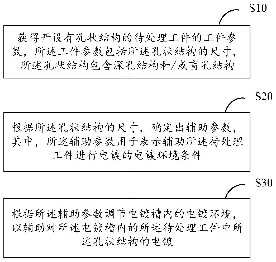
The invention provides an electroplating method, device and equipment and a storage medium. The method comprises the steps of obtaining workpiece parameters of a workpiece to be treated with a porousstructure, wherein the workpiece parameters comprise sizes of the porous structure, and the porous structure comprises a deep hole structure and / or blind hole structure; according to the size of the porous structure, determining auxiliary parameters, wherein the auxiliary parameters are used for showing electroplating environment conditions for assisting electroplating of the workpiece to be treated; and according to the auxiliary parameters, adjusting the electroplating environment in an electroplating tank to assist electroplating of the porous structure in the workpiece to be treated in theelectroplating tank. Proper auxiliary parameters can be determined for sizes of the different deep hole structures and / or blind hole structures, the electroplating environment in the electroplating tank is regulated, and electroplating quality stability is ensured.

Description

technical field [0001] The present application relates to the technical field of electroplating, in particular, to an electroplating method, device, equipment and storage medium. Background technique [0002] Electroplating technology is to use the principle of electrolysis to plate a thin layer of other metals or alloys on some metal surfaces to obtain some properties of the plated metal, such as preventing metal oxidation (such as rust), improving wear resistance, electrical conductivity, Reflective properties, corrosion resistance (copper sulfate, etc.) and aesthetic enhancement, etc. [0003] With the development of aerospace, ships, deep sea and other fields, the functions of the devices used in these fields are becoming more and more diversified, and the appearance of deep hole and blind hole structure makes the structure of the workpiece more and more complex, which affects the material itself. The performance (such as corrosion resistance) requirements are getting h...

Claims


Application Information

Patent Timeline
IPC IPC(8): C25D21/12C25D7/04C25D17/00C25D5/20C25D21/02C25D21/04C25D5/08
CPCC25D5/08C25D5/20C25D7/04C25D17/00C25D21/02C25D21/04C25D21/12
Inventor 邹本辉
Owner 苏州融睿电子科技有限公司
Learn More