
Temperature and direction recognizable curvature sensing optical fiber and manufacturing and using method thereof

A technology for direction identification and sensing optical fibers, which is applied in the directions of multi-layer core/clad optical fibers, thermometers, clad optical fibers, etc. Placement difficulties and other problems to achieve the effect of not easy to oxidize

Pending Publication Date: 2020-07-28
CHONGQING THREE GORGES UNIV
View PDF0 Cites 10 Cited by
  • Summary
  • Abstract
  • Description
  • Claims
  • Application Information

AI Technical Summary

Problems solved by technology

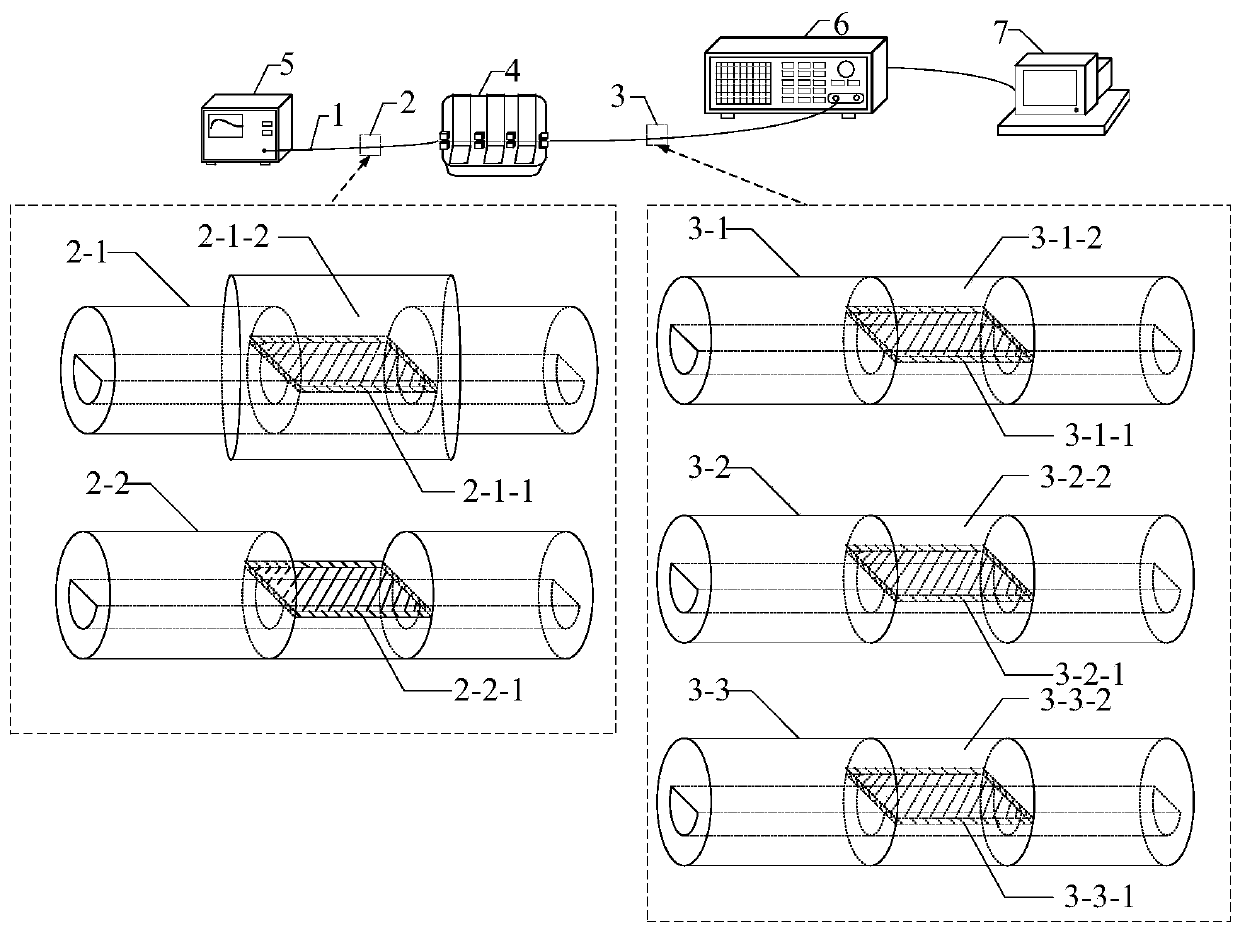
[0007] In view of this, the object of the present invention is to provide a temperature and direction-recognizable curvature sensing optical fiber and a method for making and using it. The present invention can solve the problem that the stability of the sensor decreases due to the stripping of the coating layer and the cladding of the traditional optical fiber. , the present invention can also be placed in a PDMS microfluidic chip, which solves the difficulty of placing a fiber optic microfluidic channel thermometer and cannot measure the temperature in the microfluidic channel and other positions in real time, and can also be placed in an electronic product insulated by potting glue for temperature measurement. Measurement, the present invention can not only carry out the temperature sensing of solid liquid, but also can carry out bending curvature measurement and direction judgment, also realized multi-point temperature, curvature measurement and direction judgment based on wavelength division multiplexing technology, in biomedicine, electronic chip Monitoring, landslides in the Three Gorges Reservoir area, reservoir banks and other geological environment monitoring fields have good application prospects

Method used


Image

  • Temperature and direction recognizable curvature sensing optical fiber and manufacturing and using method thereof
  • Temperature and direction recognizable curvature sensing optical fiber and manufacturing and using method thereof
  • Temperature and direction recognizable curvature sensing optical fiber and manufacturing and using method thereof

Examples


Embodiment Construction

[0043] Embodiments of the present invention are described below through specific examples, and those skilled in the art can easily understand other advantages and effects of the present invention from the content disclosed in this specification. The present invention can also be implemented or applied through other different specific implementation modes, and various modifications or changes can be made to the details in this specification based on different viewpoints and applications without departing from the spirit of the present invention. It should be noted that the diagrams provided in the following embodiments are only schematically illustrating the basic concept of the present invention, and the following embodiments and the features in the embodiments can be combined with each other in the case of no conflict.

[0044] Wherein, the accompanying drawings are for illustrative purposes only, and represent only schematic diagrams, rather than physical drawings, and should...


PUM

PropertyMeasurementUnit
Diameteraaaaaaaaaa
Thicknessaaaaaaaaaa
Refractive indexaaaaaaaaaa

Abstract

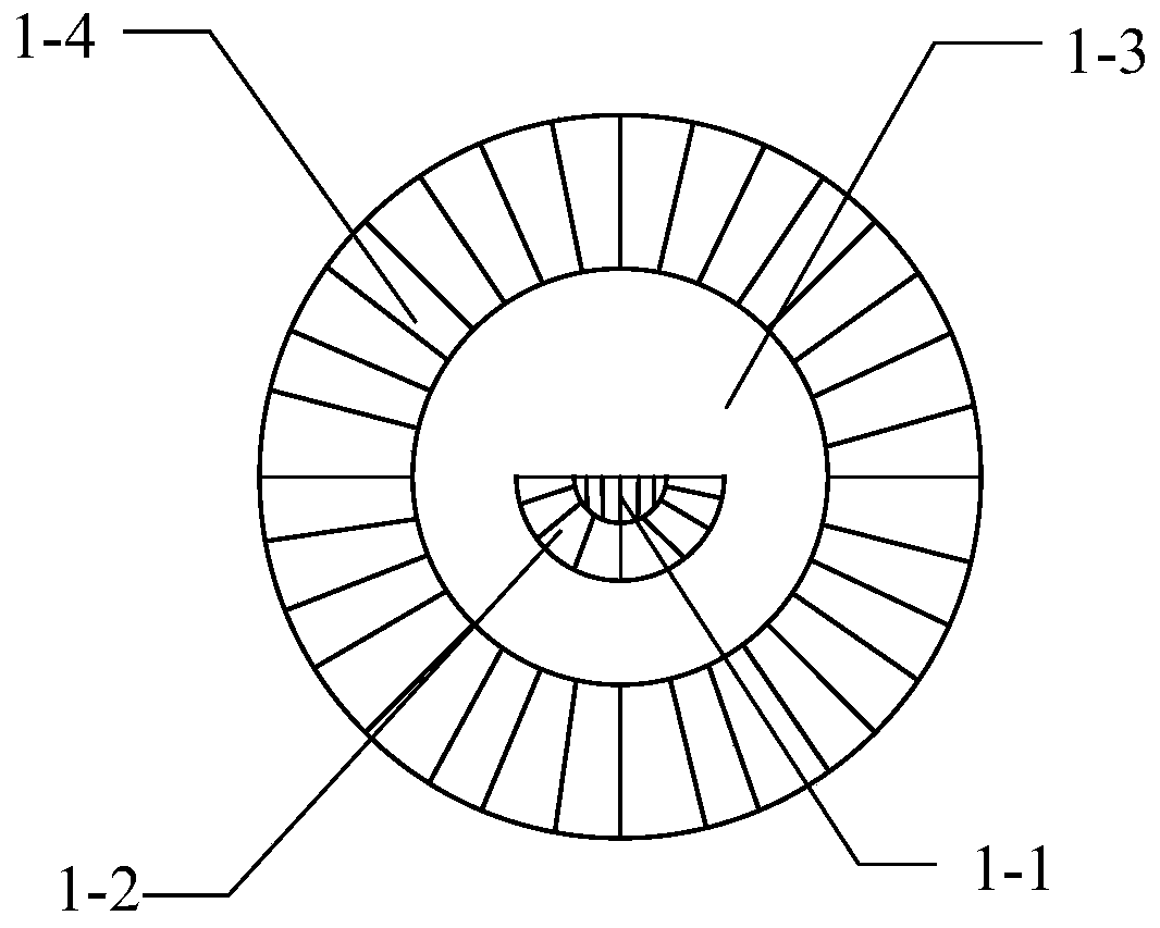
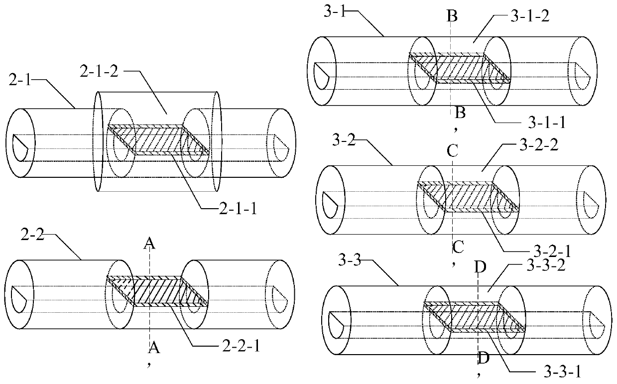
The invention belongs to the field of optical fiber sensing, and mainly relates to a temperature and direction recognizable curvature sensing optical fiber. A double-clad D-shaped multimode optical fiber with a semi-circular quartz cladding and an annularly-clad low-refractive-index plastic cladding is prepared through precision side grinding of an optical fiber preform and secondary pressure coating; the coating layer and the plastic cladding are mechanically peeled off, an SPR sensing film is plated, the restored optical fiber is reshaped by using a low-refractive-index liquid or a low-refractive-index coating adhesive, and an SPR sensing module is manufactured on the restored optical fiber; the optical fiber is novel and stable in structure, and high in bending performance, liquid and solid environment temperature measurement can be carried out through the resonance wavelength; multi-point simultaneous measurement based on the wavelength division multiplexing technology can also becarried out; curvature measurement, bending direction judgment and multi-point simultaneous measurement based on the wavelength division multiplexing technology can be carried out through two parameters of resonance wavelength and resonance valley depth, and the optical fiber and the method have a good application prospect in the fields of biomedicine, electronic chip monitoring, three gorges reservoir area landslide, reservoir banks and other geological environment monitoring.

Description

technical field [0001] The invention belongs to the field of optical fiber sensors, and in particular relates to a temperature and direction-identifiable curvature sensing optical fiber and a method for making and using it. Background technique [0002] Surface plasmon resonance (SPR) sensors have the advantages of small size, high sensitivity, resistance to electromagnetic radiation and interference, and long-distance measurement. They are widely used in food safety, biomedicine, and environmental monitoring. The principle is: when a light wave shoots from an optically dense medium to an optically sparse medium, reflection and refraction will occur at the interface of the two media. If the incident angle is greater than the critical angle, no refraction will occur, and the energy of the reflected light wave is equal to that of the incident light wave. , this phenomenon is called total reflection. When total reflection occurs, after the incident light hits the interface betw...

Claims


Application Information

Patent Timeline
IPC IPC(8): G01B11/24G01D5/353G01K11/32G02B6/02G02B6/036
CPCG01B11/24G01D5/35354G01K11/32G02B6/02033G02B6/03622
Inventor 魏勇李玲玲刘春兰胡江西吴萍赵晓玲苏于东李波
Owner CHONGQING THREE GORGES UNIV
Learn More