Jacket type composite additive manufacturing device

An additive manufacturing and cladding technology, applied in the field of additive manufacturing, can solve the problems of low forming efficiency, high replacement difficulty, low material utilization rate, etc., to reduce manufacturing cost and production cycle, stabilize consistency and stability, The effect of reducing the risk of unevenness

Inactive Publication Date: 2020-07-31
AVIC BEIJING AERONAUTICAL MFG TECH RES INST
View PDF6 Cites 6 Cited by
  • Summary
  • Abstract
  • Description
  • Claims
  • Application Information

AI Technical Summary

Problems solved by technology

[0003] Although the existing additive manufacturing device has certain advantages, it has the following disadvantages: (1) powder or wire material is used, which has high cost, low forming efficiency and low precision; (2) it is difficult to replace and connect wire coils, If one roll of wire is used up and another roll is replaced, necessary shutdown and precisely controlled wire threading process are required. This work is relatively easy in the atmospheric environment, but usually the forming is carried out in a sealed forming cabin, so the replacement is difficult. It is relatively large, and it is also difficult to meet the stability of additive materials and the requirements of metallurgical co-furnace; (3) the composite forming of conventional direct deposition + rolling or micro-forging, the equipment is essentially based on point-shaped molten pool deposition and forming to improve its An additional one-dimensional pressure treatment method for high performance can refine the grains of the local structure to a certain extent, but the free ends on both sides are still in the cast structure due to unconstrained, the forming accuracy is low, and the material utilization rate is low; (4 ) The conventional device inherits the characteristics of surfacing welding and lacks the necessary metallurgical device to carry out sufficient metallurgical process, so that the metallurgical defects of the metal components formed by additive forming are obvious, and it is difficult to make up for it through post-processing

Method used


Image

  • Jacket type composite additive manufacturing device
  • Jacket type composite additive manufacturing device
  • Jacket type composite additive manufacturing device

Examples


Embodiment 1

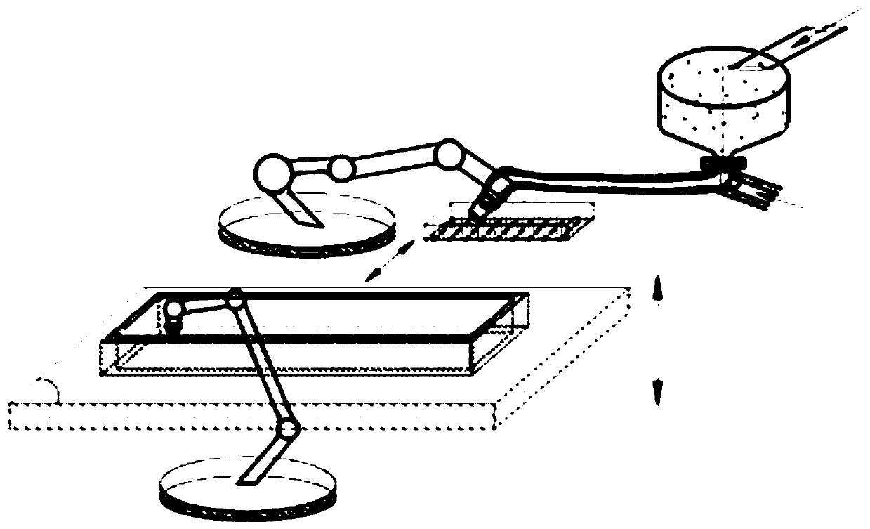
[0054] see Figure 7 , when a large metal component has a large cross-section and a small thickness, it can be manufactured in a block-by-block manner, that is, on the same base 11, at least two claddings 10 are deposited by the deposition forming device 13, and all claddings 10 are stacked horizontally, and then the molten metal is cast into all claddings 10 one by one through the casting forming device 15 .

Embodiment 2

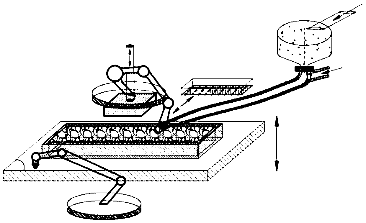
[0056] see Figure 8 , when a large metal component has a small cross-section and a relatively high thickness, it can be manufactured in a layered stacking manner, that is, on the same base 11, at least two stacked claddings 10 are deposited by the deposition forming device 13, and then The molten metal is cast into all claddings 10 one by one by means of the casting device 15 .

Embodiment 3

[0058] see Figure 9 Specifically, in this embodiment, the cross-sectional shape of the cladding 10 is cross-shaped. It can be understood that, in other embodiments, the cross-sectional shape of the casing 10 can also be a regular shape such as a polygon, a circle, or an ellipse.


PUM


Abstract

The invention discloses a jacket type composite additive manufacturing device. The jacket type composite additive manufacturing device comprises a sealed forming cabin and a base arranged in the sealed forming cabin, wherein a jacket deposition forming device is arranged on one side of the base, a casting forming device is arranged on the other side of the base, an extruding/forging/rolling mechanical auxiliary device is arranged over the base, the casting forming device is connected with a metal smelting device through a flow guide pipe, the metal smelting device communicates with the flow guide pipe through a flow control element, and when metal liquid in a jacket is cooled to the proper pressure machining temperature, the metal liquid in the jacket is subjected to combined machining through the device. According to the jacket type composite additive manufacturing device, through the casting forming device, conventional wire and powder base metal is replaced with large-block base metal, the sufficiency of metal metallurgy is improved through the metal smelting device, a deposited blank is subjected to three-way extrusion stress, the action mode of an existing deposition and one-dimensional composite additive forming device is changed, the consistency and stability of a structure and performance of a formed component are greatly improved, the manufacturing efficiency is greatly improved, and the manufacturing cost is reduced.

Description

technical field [0001] The invention relates to the technical field of additive manufacturing, in particular to an cladding type composite additive manufacturing device. Background technique [0002] At present, the process method of additive manufacturing metal components inherits the process route characteristics of "point-line-surface-body" of surfacing welding. The additive manufacturing device uses feeding wire or powder as raw material, and uses manipulator or machine tool as carrier. Carry the welding head to achieve the purpose of forming through the method of multi-layer and multi-channel digital surfacing. [0003] Although the existing additive manufacturing device has certain advantages, it has the following disadvantages: (1) powder or wire material is used, which has high cost, low forming efficiency and low precision; (2) it is difficult to replace and connect wire coils, If one roll of wire is used up and another roll is replaced, necessary shutdown and prec...

Claims


Application Information

Patent Timeline
Patent Type & Authority Applications(China)
IPC IPC(8): B22F3/105B22D19/00B33Y10/00B33Y30/00
CPCB22D19/00B33Y10/00B33Y30/00B22F10/00B22F10/73B22F10/25B22F12/38B22F12/222B22F10/32Y02P10/25
Inventor 单飞虎刘琦李怀学王玉岱
Owner AVIC BEIJING AERONAUTICAL MFG TECH RES INST
Why Eureka
Try Eureka