Waste heat recovery system and method for coal-fired power plant

A waste heat recovery system, a technology for coal-fired power plants, applied in combustion methods, preheating, feed water heaters, etc., can solve the problem of high energy consumption in the recovery system

Pending Publication Date: 2020-08-04
DATANG ENVIRONMENT IND GRP +1
View PDF0 Cites 6 Cited by
  • Summary
  • Abstract
  • Description
  • Claims
  • Application Information

AI Technical Summary

Problems solved by technology

[0005] The first purpose of the present invention is to provide a waste heat recovery system of a coal-fired power station, which can solve the problem of high energy consumption of the recovery system;

Method used


Image

  • Waste heat recovery system and method for coal-fired power plant

Examples


Embodiment Construction

[0033] The technical solutions of the present invention will be clearly and completely described below in conjunction with the embodiments. Obviously, the described embodiments are part of the embodiments of the present invention, but not all of them. Based on the embodiments of the present invention, all other embodiments obtained by persons of ordinary skill in the art without making creative efforts belong to the protection scope of the present invention.

[0034] In describing the present invention, it is to be understood that the terms "center", "longitudinal", "transverse", "length", "width", "thickness", "upper", "lower", "front", " Back", "Left", "Right", "Vertical", "Horizontal", "Top", "Bottom", "Inner", "Outer", "Clockwise", "Counterclockwise", etc. or The positional relationship is based on the orientation or positional relationship shown in the drawings, which is only for the convenience of describing the present invention and simplifying the description, rather t...


PUM


Abstract

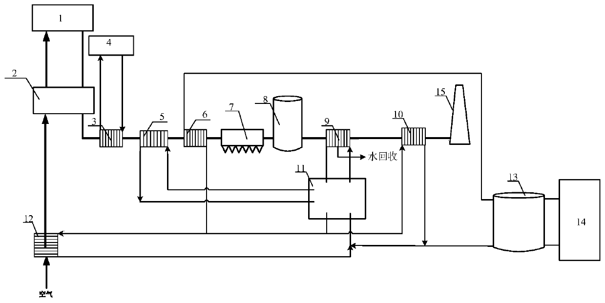
The invention provides a waste heat recovery system for a coal-fired power plant. The waste heat recovery system involves a boiler, an air preheater, a plurality of coolers, a dust remover, a desulfurizing tower, a flue gas condensation heat exchanger, a flue gas reheater and a chimney which are sequentially arranged; the plurality of coolers are sequentially connected in series, the outlet temperatures of heat exchange media of the plurality of coolers are sequentially reduced, and the plurality of coolers correspond to different heat using devices; the system involves an absorption heat pump, a thermocline heat storage tank and a heat supply network, and the hot water output end of the thermocline heat storage tank communicates with the heat supply network; and heat generated by part ofthe coolers is used for driving the absorption heat pump to recover heat released in the flue gas condensation process, part of the heat generated by the heat pump is conveyed to the flue gas reheaterto be used for reheating flue gas, part of the heat is used for preheating air, and the rest part of the heat is continuously heated in part of coolers and stored in the thermocline heat storage tankto supply heat loads needed by the heat supply network. Gradient utilization of energy is achieved, energy conservation, water recovery and thermoelectric decoupling can be achieved simultaneously, and the unit waste heat and water recovery capacity and the power station operation flexibility are improved.

Description

technical field [0001] The invention relates to the technical field of waste heat recovery of coal-fired power stations, in particular to a waste heat recovery system and method for coal-fired power stations. Background technique [0002] Coal is still the main energy source in the world, and coal-fired power generation is the main way of coal utilization. Improving the efficiency and operational flexibility of coal-fired power plants, reducing pollutant emissions and resource consumption are long-term concerns for coal-fired power plants. At the same time, the thermal load and electrical load of the combined heat and power unit are coupled with each other, resulting in poor peak-shaving capability of the power station and poor unit flexibility. [0003] Coal is still the main energy source in the world, and coal-fired power generation is the main way of coal utilization. Improving the efficiency and operational flexibility of coal-fired power plants, reducing pollutant em...

Claims


Application Information

Patent Timeline
Patent Type & Authority Applications(China)
IPC IPC(8): F23J15/06F22D1/00F23L15/00F25B15/00F25B27/02
CPCF22D1/00F23J15/06F23L15/00F25B15/00F25B27/02Y02B30/625Y02E20/34Y02A30/274
Inventor 张国柱崔焕民张钧泰文钰刘忠秋
Owner DATANG ENVIRONMENT IND GRP
Why Eureka
Try Eureka