Team-forming welding production system for crane girder webs

A main girder web and production system technology, applied in welding equipment, welding equipment, auxiliary welding equipment, etc., can solve the problems of harsh manual welding environment, low work efficiency, low welding efficiency, etc., and achieve fast and accurate assembly and formation. The effect of reducing manpower loss and improving hoisting efficiency

Active Publication Date: 2020-08-11
HENAN WEIHUA HEAVY MACHINE
View PDF8 Cites 2 Cited by
  • Summary
  • Abstract
  • Description
  • Claims
  • Application Information

AI Technical Summary

Problems solved by technology

[0002] The main girder of the crane is generally a box structure. As the main load-bearing part of the whole machine, it is mainly composed of upper and lower cover plates, webs on both sides and ribs in the middle of the beam box; the welding sequence of the main girder is generally to first weld several The arranged ribs and the lower cover are welded and positioned, and then the webs are grouped through the fixture, and then the webs and the ribs, the webs and the cover are spot welded or broken welded for positioning, and the main girder internal welding is carried out for the next step Welding of the seam should be prepared; because the length of the web of the crane is long and it is a plate splicing structure, the plates of the main girder web need to be tailor-welded before assembly, and the tailor-welding station can ensure that the web is assembled The waviness after welding; however, when the tailor-welded web is welded together with the cover plate an

Method used


Image

  • Team-forming welding production system for crane girder webs
  • Team-forming welding production system for crane girder webs
  • Team-forming welding production system for crane girder webs

Examples


Embodiment Construction

[0028] The present invention can be explained in detail by the following examples, and the purpose of disclosing the present invention is intended to protect all technical improvements within the scope of the present invention, and the present invention is not limited to the following examples; in the description of the present invention, it needs to be understood Yes, if there are orientations or positional relationships indicated by the terms "upper", "lower", "front", "rear", "left", "right", etc., they only correspond to the drawings of this application, for the convenience of describing this invention, without indicating or implying that the device or element referred to must have a particular orientation:

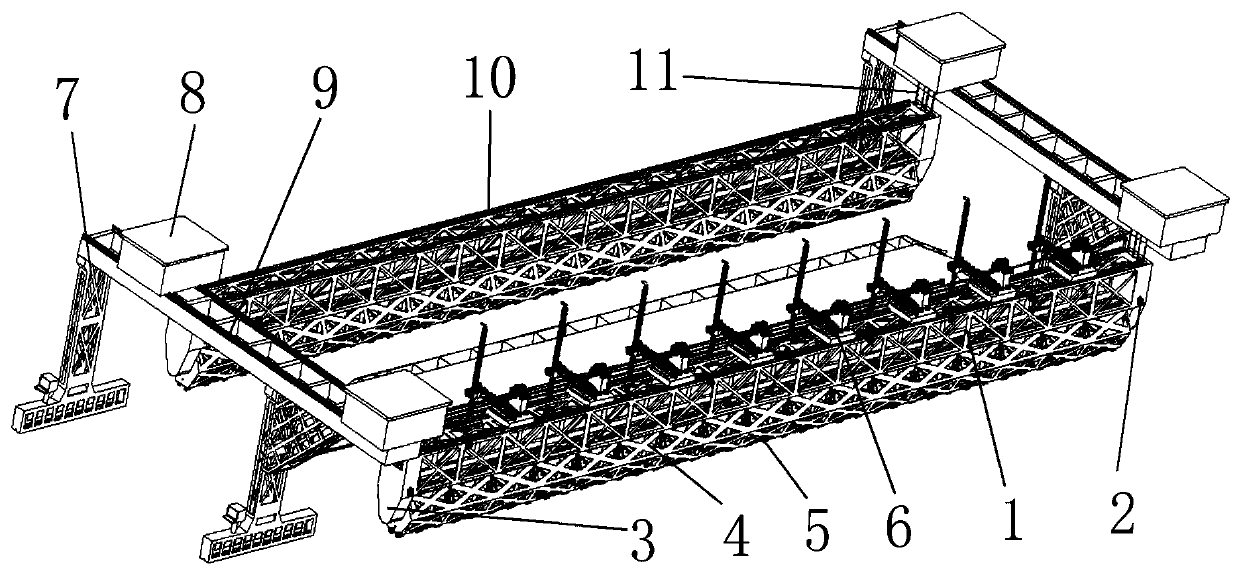
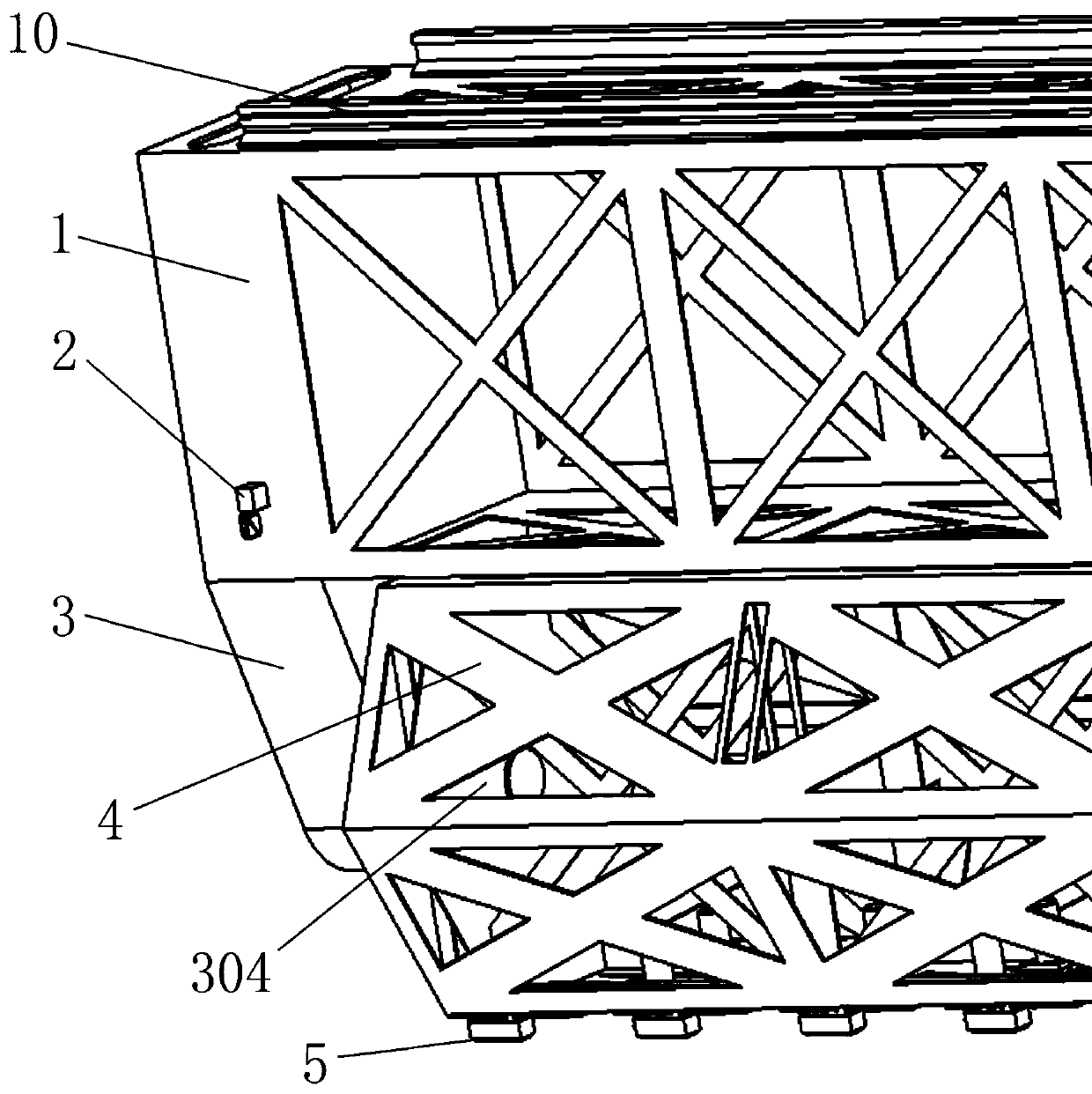
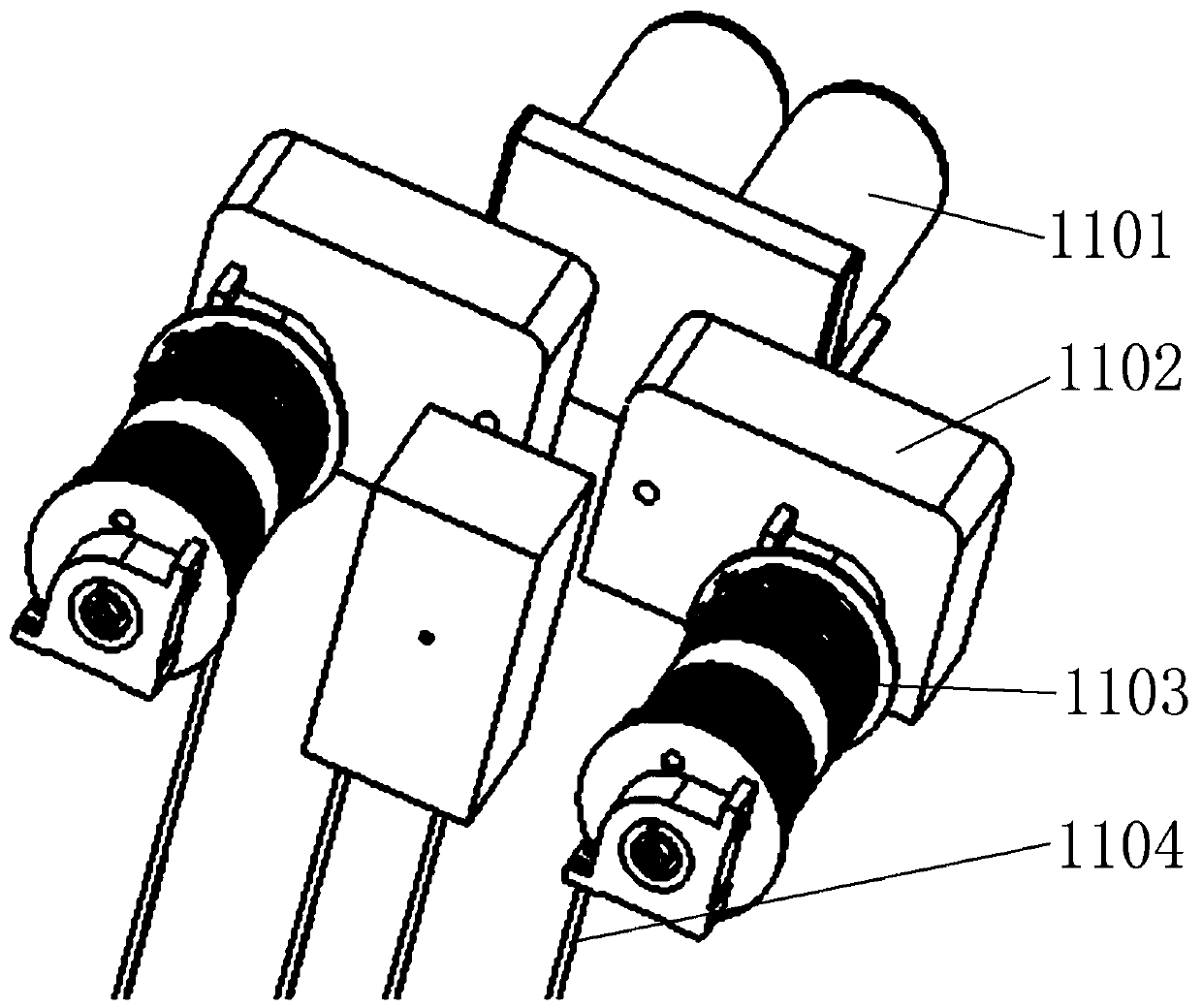
[0029] combined with Figure 1-9The team welding production system of the main girder web of the crane includes a hanging beam 1 and a rotating plate frame 4 whose axial direction is parallel to the longitudinal direction of the main girder of the crane, and two porta...


PUM


Abstract

The invention relates to the field of crane bridge welding and manufacturing, in particular to a team-forming welding production system for crane girder webs. The team-forming welding production system comprises hanging beams, rotating plate frames and two portal frames, wherein the two portal frames comprise top beams, motor home sliding rails are arranged on the upper surfaces of the top beams,house type trolleys are mounted on the motor home sliding rails, and vertical hoisting mechanisms used for synchronously hoisting the hoisting beams are arranged in the two house type trolleys; robotsliding rails are arranged on the upper surfaces of the hanging beams, and assembly welding robots are mounted on the robot sliding rails; and two lifting lug boxes are symmetrically fixed to the twoends of the lower surfaces of the hinging beams, the inner sides of the bottom ends of the two lifting lug boxes are correspondingly and rotationally connected with the two ends of the rotating plateframes, and a plurality of magnetic attraction assemblies used for attracting the webs are evenly arranged on the lower surface of the rotating plate frames in the axial direction of the rotating plate frames. The team-forming welding production system can complete automatic welding of longitudinal welding seams between the webs and cover plates and welding seams between the webs and rib plates inthe vertical direction after the webs are rapidly and accurately hoisted and positioned.

Description

technical field [0001] The invention relates to the field of crane bridge welding manufacturing, in particular to a team welding production system for the web of the main girder of the crane. Background technique [0002] The main girder of the crane is generally a box structure. As the main load-bearing part of the whole machine, it is mainly composed of upper and lower cover plates, webs on both sides and ribs in the middle of the beam box; the welding sequence of the main girder is generally to first weld several The arranged ribs and the lower cover are welded and positioned, and then the webs are grouped through the fixture, and then the webs and the ribs, the webs and the cover are spot welded or broken welded for positioning, and the main girder internal welding is carried out for the next step Welding of the seam should be prepared; because the length of the web of the crane is long and it is a plate splicing structure, the plates of the main girder web need to be ta...

Claims


Application Information

Patent Timeline
IPC IPC(8): B23K31/02B23K37/047
CPCB23K31/02B23K37/047
Inventor 刘永刚武超金瑞莹崔鹏陈爱梅
Owner HENAN WEIHUA HEAVY MACHINE
Why Eureka
Try Eureka