
Eureka
For R&D, Eureka makes reading and utilizing patents & technical documents easy.
Eureka AIR
Designed for self-driven R&D workflows. Generate viable solutions, solve complex R&D challenges, empower your innovation with AI.

Eureka Materials
Designed for material experts only. Revolutionize your material R&D, from search, analyze, to developing new materials.

TechResearch
Generate reliable direction feasibility study reports for your R&D in just a few steps.

TechSeek
Discover and master advanced knowledge NOW. Basics, ideas, possibilities, all at once.

TechMind
As an expert in R&D Theories, TechMind can generates customized viable solutions instantly.

TechRisk
Analyze your overall solution with one click, know your potential R&D risks in advance.

TechMonitor
Get weekly tech updates, stay abreast of the latest tech innovations and key insights.
Laser beam splitter
A laser beam splitter and crown-shaped technology, applied in the field of optical devices, can solve the problems of device application limitations and harsh device processing conditions, and achieve the effects of reducing feature size, good energy uniformity, and large structural processing tolerances
- Summary
- Abstract
- Description
- Claims
- Application Information
AI Technical Summary
Problems solved by technology
Method used
Image

Examples
Embodiment 1
[0029] A laser beam splitter, implemented as follows:
[0030] (1) The device material is an optical plastic with a refractive index of 1.51, specifically an optical UV-curable polymer;
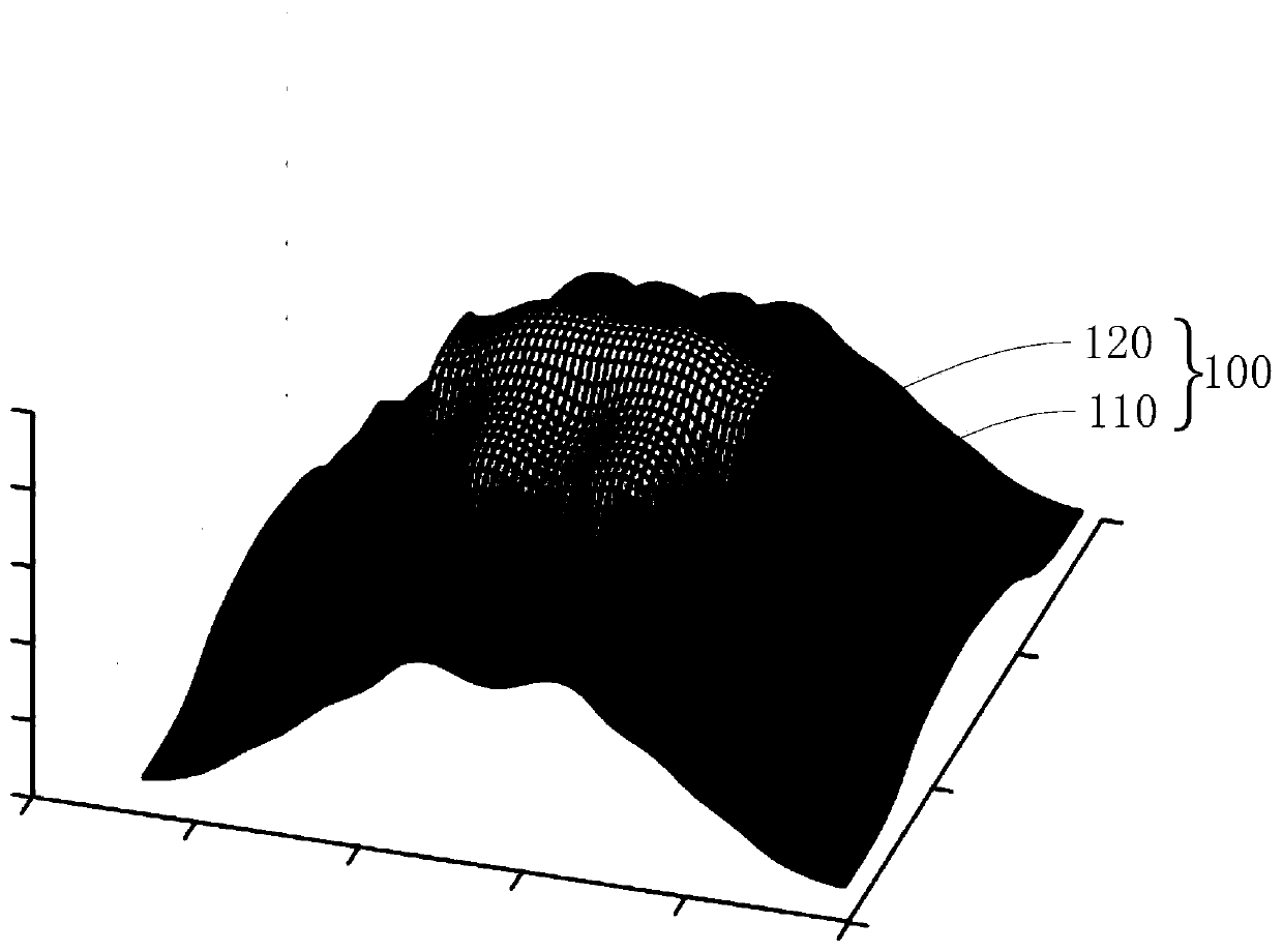
[0031] (2) The three-dimensional surface shape of the unit structure on the surface of the laser beam splitter is figure 1 The convex head crown structure shown is composed of two steep cliffs 110 and a continuous spline surface 110, and the convex head crown structure satisfies axisymmetric distribution in both horizontal and vertical directions.
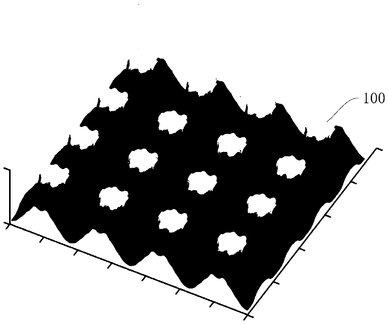
[0032] (3) by figure 1 The array of convex head-crown structures such as figure 2 As shown, the period of the array structure in the horizontal direction is 5.7 microns, the period in the vertical direction is 8.7 microns, and the height of the structure is 4.1 microns;
[0033] (4) Under the incidence of collimated laser with a wavelength of 940nm, after multi-level diffraction, the laser beam splitting effect generated on a plane with a dist...
Embodiment 2
[0037] A laser beam splitter, implemented as follows:
[0038] (1) The device material is quartz glass with a refractive index of 1.45;
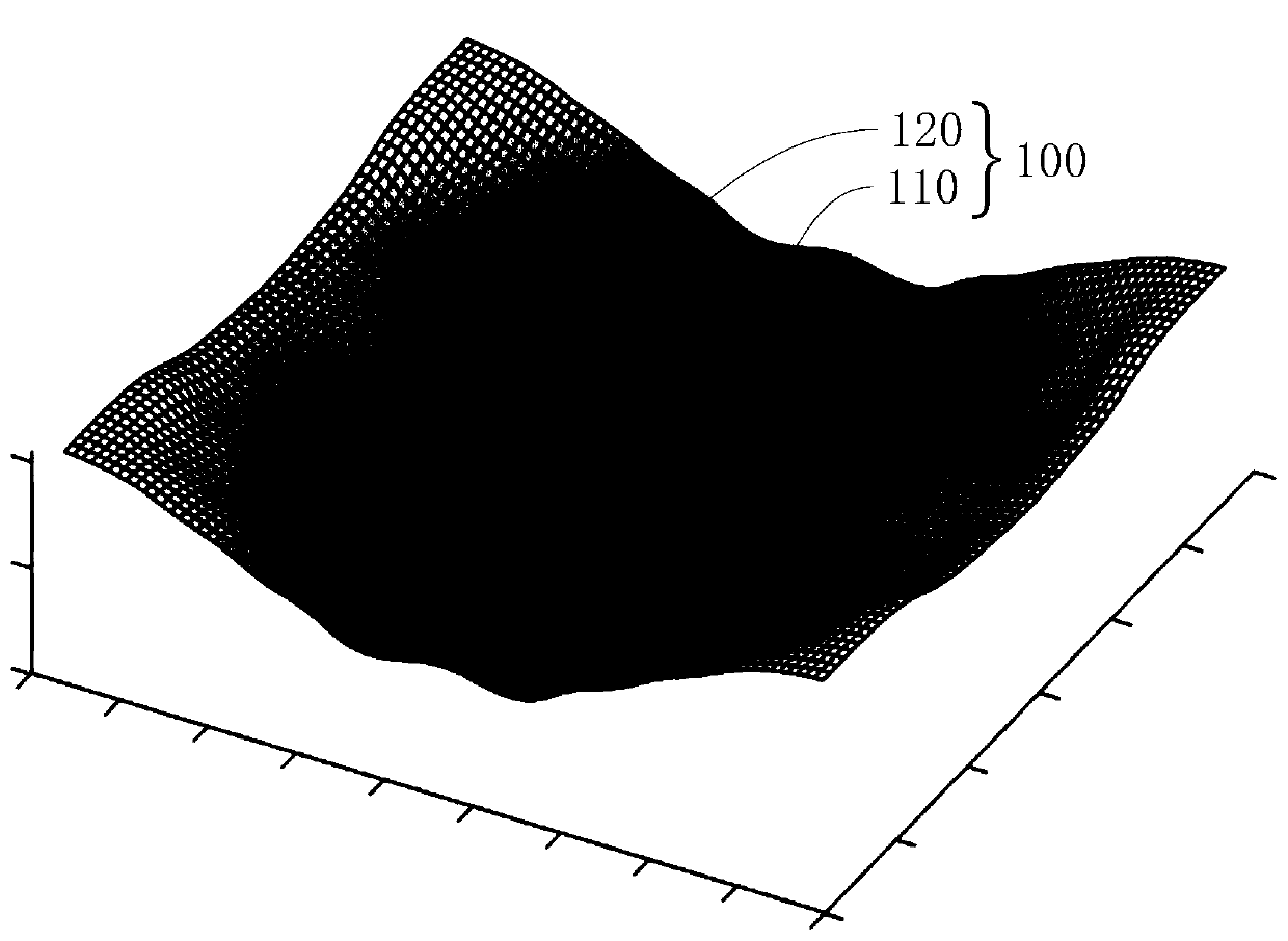
[0039] (2) The three-dimensional surface shape of the laser beam splitter unit structure is image 3 The concave head crown structure shown is composed of two steep cliffs 110 and a continuous spline surface 110, and the concave head crown structure satisfies axisymmetric distribution in both horizontal and vertical directions.
[0040] (3) by image 3 The array of concave head-crown structures such as Figure 4 As shown, the period of the array structure in the horizontal direction is 6.1 microns, the period in the vertical direction is 9.1 microns, and the height of the structure is 4.64 microns;
[0041] (4) Under the incident collimated laser with a wavelength of 940nm, after multi-level diffraction, it is divided into 7×11 beams of laser light. The energy distribution of each level is controlled by the unit concave head crown structu...
PUM
| Property | Measurement | Unit |
|---|---|---|
| Length | aaaaa | aaaaa |
| Length | aaaaa | aaaaa |
| Height | aaaaa | aaaaa |
Abstract
Description
Claims
Application Information
 - R&D Engineer
- R&D Manager
- IP Professional
- Industry Leading Data Capabilities
- Powerful AI technology
- Patent DNA Extraction
Browse by: Latest US Patents, China's latest patents, Technical Efficacy Thesaurus, Application Domain, Technology Topic, Popular Technical Reports.
© 2024 PatSnap. All rights reserved.Legal|Privacy policy|Modern Slavery Act Transparency Statement|Sitemap|About US| Contact US: help@patsnap.com