Data analysis system based on Internet of Things

A data analysis and Internet of Things technology, applied in the field of information transmission, can solve problems such as the limited scope of promotion, detection and role of the agricultural Internet of Things, and the inability to use large-scale farmland, so as to improve the scope of data collection and avoid stunted growth. , Improve the effect and accuracy of data analysis

Active Publication Date: 2020-08-14
山童(北京)科技有限公司
View PDF10 Cites 0 Cited by
  • Summary
  • Abstract
  • Description
  • Claims
  • Application Information

AI Technical Summary

Problems solved by technology

[0003] The existing patent No. CN106465659B proposes a plant growth monitoring and protection device, which realizes automation, can effectively protect plants from damage, and has various functions. The monitoring position is adjusted, and it is fixed when used, and the detection range is limited, so it cannot be used on a large scale of farmland
[0004] The existing patent number CN107125059A proposes an agricultural greenhouse control system based on the Internet of Things, which has the advantag

Method used


Image

  • Data analysis system based on Internet of Things
  • Data analysis system based on Internet of Things
  • Data analysis system based on Internet of Things

Examples


Embodiment 1

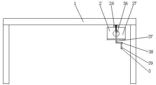
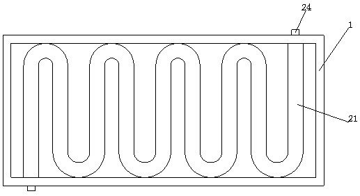
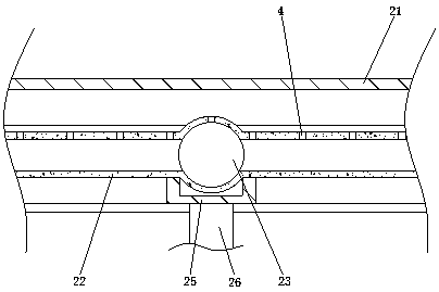
[0047] Example 1: Please refer to Figure 1-8 , a system based on the data analysis of the Internet of Things, including a fixed frame 1, a moving mechanism 2 and a detection mechanism 3, the top surface of the fixed frame 1 is hollowed out, and the moving mechanism 2 is fixedly installed on the inner wall of the fixed frame 1, and the moving mechanism 2 includes Guide rail 21, rubber cylinder 22, rolling ball 23, trachea joint 24, clamp ring 25, connecting plate 26 and detection box 27, the shape of guide rail 21 is wave type body and internal hollow, the middle part of guide rail 21 bottom surface is semi-cylindrical and the center Hollow out, the inner wall of the middle part of the guide rail 21 is socketed with the rubber cylinder 22, the inside of the rubber cylinder 22 is hollow and distributed along the guide rail 21, the inner wall of the rubber cylinder 22 is socketed with the rolling ball 23, and the diameter of the rolling ball 23 is the diameter of the inner wall o...

Embodiment 2

[0050] Example 2: Please refer to Figure 9-16 , on the basis of Embodiment 1, two adjustment mechanisms 8 are fixedly installed in the detection box 27, and the adjustment mechanism 8 includes a heating box 81, a conduit 82, a cylinder B83, a piston B84, a spring B85, a piston rod B86, and a linkage rod 87 , convex ball B88, expansion plate A89, expansion plate B810, cylinder C811, piston C812, piston rod C813, bolt 814, connecting pipe 815, sector plate 816, round rod 817, stirring rod 818, friction plate 819, cylinder D820 , piston D821, spring C822, piston rod D823, spring D824, baffle plate 825 and PH drug cartridge 826, the heating box 81 is fixedly connected to the position at the two ends of the guide rail 21 on the outer wall of the fixed frame 1, and the inside of the heating box 81 is fixedly installed with a heating tube and It is electrically connected with the control electric box 320, the heating box 81 communicates with the rubber cylinder 22, and a gas pipe jo...


PUM


Abstract

The invention relates to the technical field of information transferring, and discloses a data analysis system based on the Internet of Things. The data analysis system based on the Internet of Thingscomprises a fixing frame, a moving mechanism and detection mechanisms, wherein the top surface of the fixing frame adopts a hollow state; the moving mechanism is fixedly mounted on the inner wall ofthe fixing frame; the moving mechanism comprises a guide rail, a rubber barrel, a rolling ball, gas pipe fittings, a clamp ring, a connecting plate and a detection tank; the middle part of the bottomsurface of the guide rail is a semicylinder and the center is hollow; the inner wall of the middle part of the guide rail is in sleeving connection with the rubber barrel; the inner wall of the rubberbarrel is in sleeving connection with the rolling ball; two ends at the guide rail, of the fixing frame are separately and fixedly connected with gas pipe fittings; two side surfaces of the clamp ring are in sleeving connection with a rubber barrel; the rolling ball is arranged corresponding to the center of the clamp ring; the bottom surface of the clamp ring is fixedly connected with the connecting plate; and the bottom surface of the connecting plate is fixedly connected with the detection tank. Compared with a conventional data acquiring manner, the moving mechanism is arranged, so that the data analysis system based on Internet of Things can move on the farmland to enlarge detection range, requirements for knowledge and techniques of a user are low, and popularizing and using of agriculture Internet of Things are facilitated.

Description

technical field [0001] The invention relates to the technical field of information transmission, in particular to a data analysis system based on the Internet of Things. Background technique [0002] In the application of the Internet of Things in agriculture, it is necessary to use temperature sensors, humidity sensors, PH value sensors, illuminance sensors, CO2 sensors and other equipment to detect the temperature, relative humidity, PH value, light intensity, soil nutrients, CO2 concentration, etc. in the environment. The physical quantity parameters ensure that the crops have a good and suitable growth environment. [0003] The existing patent No. CN106465659B proposes a plant growth monitoring and protection device, which realizes automation, can effectively protect plants from damage, and has various functions. The monitoring position is adjusted, and it is fixed when used, and the detection range is limited, so it cannot be used in a large area of ​​farmland. [000...

Claims


Application Information

Patent Timeline
IPC IPC(8): A01G25/16A01M7/00G01N33/24G05D27/02B01F7/00B01F7/18C02F1/66
CPCA01G25/16A01G25/167A01M7/0089G01N33/24G05D27/02C02F1/66G01N2033/245B01F27/00B01F27/90
Inventor 孙晶王友权黄静
Owner 山童(北京)科技有限公司
Why Eureka
Try Eureka