Working method of automatic coil feeding device for steel coil rolling

A technology of a coil feeding device and a working method, which is applied in the directions of manufacturing tools, metal processing equipment, metal wire drawing, etc., can solve the problems of reducing the tightening effect of the inner ring of the steel coil, unfavorable to the production and use of the steel coil, and affecting the fixing effect, etc. Improve fixing effect, save manpower and time, reduce internal stress

Active Publication Date: 2020-08-14
内蒙古包钢同业金属新材料有限公司
View PDF8 Cites 5 Cited by
  • Summary
  • Abstract
  • Description
  • Claims
  • Application Information

AI Technical Summary

Problems solved by technology

[0006] 1. There are only a few spreader rolls designed, and the spreader cylinder is used to drive several spreader rolls to tighten the inner ring of the steel coil, so as to fix the steel coil when uncoiling, once there is a spreader roll If the sheet is damaged, the tightening effect on the inner ring of the steel coil will be reduced, and the steel coil will easily fall off, which will affect the fixing effect. Therefore, the stability of the braced structure needs to be improved
[0007] 2. Use hot oil to heat the steel strip after the steel coil is unrolled. Although the air blowing structure is designed to blow off the residual hot oil on the surface of the steel coil, the steel coil will still be polluted by oil stains, which is not conducive to steel. Post-roll production and use

Method used


Image

  • Working method of automatic coil feeding device for steel coil rolling
  • Working method of automatic coil feeding device for steel coil rolling
  • Working method of automatic coil feeding device for steel coil rolling

Examples


Embodiment Construction

[0045] The technical solutions of the present invention will be further described below in conjunction with the accompanying drawings and through specific implementation methods.

[0046] Wherein, the accompanying drawings are only for illustrative purposes, showing only schematic diagrams, rather than physical drawings, and should not be construed as limitations on this patent; in order to better illustrate the embodiments of the present invention, some parts of the accompanying drawings will be omitted, Enlarged or reduced, does not represent actual product size.

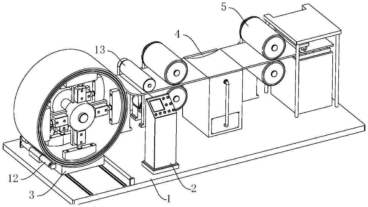
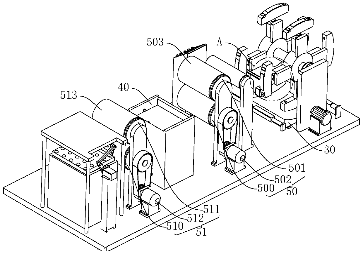
[0047] refer to Figure 1 to Figure 8 The shown automatic coil feeding device for coil uncoiling and its use method includes a base 1, and also includes a controller 2, a feeding mechanism 3, a heating mechanism 4 and a conveying mechanism 5, and the controller 2 is fixed on the base 1 The top of the top, the feeding mechanism 3 is arranged on the top of the base 1 for feeding steel coils, the feeding mechanism 3...


PUM


Abstract

The invention relates to the technical field of leveling equipment, in particular to an automatic coil feeding device for steel coil rolling and an application method of the automatic coil feeding device. The automatic coil feeding device comprises a base, a controller, a feeding mechanism, a heating mechanism and a conveying mechanism, wherein the feeding mechanism comprises a slipway, a rotatingassembly and a plurality of tight supporting assemblies; the heating mechanism comprises a heating platform and a heat supplying assembly; the conveying mechanism comprises a traction assembly, a leveling assembly and a compacting assembly; the traction assembly and the leveling assembly are symmetrically arranged at two ends of the heating platform; the compacting assembly is arranged beside theleveling assembly; and the rotating assembly, the heat supplying assembly, the traction assembly, the leveling assembly, the compacting assembly and the tight supporting assemblies are electrically connected with the controller. Through the adoption of the automatic coil feeding device for steel coil rolling and the application method of the automatic coil feeding device disclosed by the invention, steel coils can be effectively fixed, and falling of the steel coils is avoided; and besides, when the internal stress of steel belts is eliminated, the steel coils can be guaranteed to be free from pollution, and subsequent production and usage are convenient.

Description

technical field [0001] The invention relates to the technical field of flattening equipment, in particular to a working method of an automatic coil feeding device for uncoiling steel coils. Background technique [0002] Among the current technologies, steel coils are a common production raw material, such as automobile shells in the field of automobile manufacturing, various thin steel pipes, and can be directly processed into various steel plates and steel strips. When using steel coils for further processing, the coils first need to be uncoiled to form flat steel plates and cut to size. An uncoiler is required during the uncoiling process. [0003] my country's patent application number: CN201610475636.0; publication date: 2016.11.16 discloses a steel coil uncoiling production line, which belongs to the technical field of flattening equipment, which includes an unwinding device that is rotatably installed on a support frame, and downstream devices of the uncoiling devic...

Claims


Application Information

Patent Timeline
Patent Type & Authority Applications(China)
IPC IPC(8): B21C47/20B21C47/24B21C47/30B21C19/00C21D8/02C21D11/00
CPCB21C19/00B21C47/20B21C47/24B21C47/30C21D8/0242C21D8/0247C21D11/00
Inventor 段文忠苏波
Owner 内蒙古包钢同业金属新材料有限公司
Why Eureka
Try Eureka