Coke oven flue gas denitration and desulfurization waste heat utilization integrated device
A technology for coke oven flue gas and denitration, which is applied in gas treatment, indirect heat exchangers, lighting and heating equipment, etc., can solve problems such as energy waste, increase the cost of flue gas purification and treatment, and reduce the activity of SCR denitration catalysts. The effect of realizing heat recovery and improving heat recovery efficiency
- Summary
- Abstract
- Description
- Claims
- Application Information
AI Technical Summary
Problems solved by technology
Method used
Image
Examples
Embodiment 1
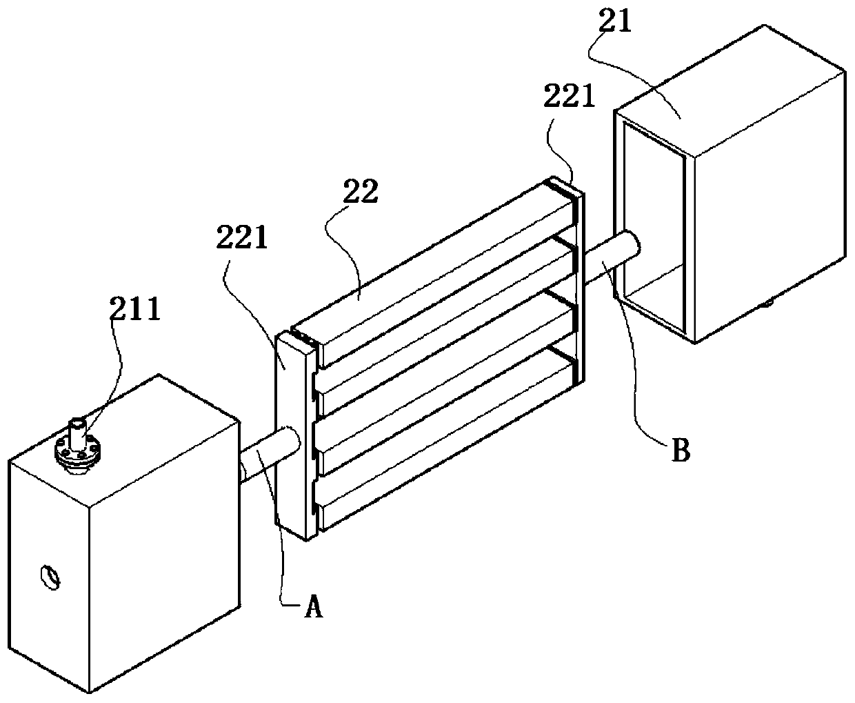
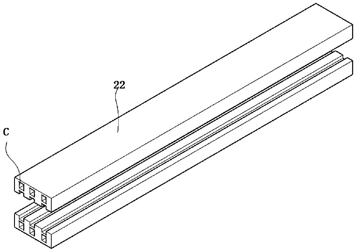
[0049] like Figure 1-8 As shown, a coke oven flue gas denitrification and desulfurization waste heat utilization integrated device includes a desulfurization tower 1, a waste heat recovery component 2 connected to the desulfurization tower 1, a primary SCR denitrification component 3 connected to the waste heat recovery component 2, and a primary SCR The secondary SCR denitrification component 4 of the denitrification component 3 , the primary dehumidifier 5 connected to the secondary SCR denitrification component 4 , and the secondary dehumidifier 6 connected to the primary dehumidifier 5 . Both the above components are connected in turn.
[0050] After the coke oven flue gas is desulfurized by the desulfurization tower 1, the heat is recovered by the waste heat recovery component 2, the temperature of the high-temperature flue gas is reduced, and then the denitration treatment is realized by the secondary SCR denitrification component 4 of the first-level SCR denitrificatio...
Embodiment 2
[0061] like Figure 1-8 As shown, in this embodiment, on the basis of the structure of Example 1, in order to achieve denitrification, the above-mentioned flue gas is denitrated through the first-level SCR denitrification component and the second-level SCR denitrification component 4, specifically, the first-level SCR denitrification component 3 and the second-level SCR The denitrification components 4 have the same structure; the primary SCR denitrification component 3 and the secondary SCR denitrification component 4 are connected through a denitrification pipeline. Specifically, the first-level SCR denitrification component 3 and the second-level SCR denitrification component 4 both include a denitrification box 34, and a cavity is arranged inside the denitrification box 34, and several SCR denitration catalyst plates 32 distributed up and down.
[0062] The flue gas enters the cavity of the nitrification box and flows through the catalytic channel in the SCR denitration c...
Embodiment 3
[0072] like Figure 1-8 As shown, in this embodiment, on the basis of the structure of Embodiment 2, in order to realize the drying of flue gas, the secondary SCR denitrification component 4 and the primary dehumidifier 5 are connected through the first dehumidification pipeline. At the same time, in order to further improve the dehumidification effect, The primary dehumidifier 5 communicates with the secondary dehumidifier 6 through a second dehumidification pipeline. The flue gas passes through the primary dehumidifier 5 and the secondary dehumidifier 6 for secondary dehumidification. Wherein, the primary dehumidifier 5 and the secondary dehumidifier 6 are conventional flue gas dehumidifiers disclosed in the prior art.
[0073] The flue gas after dehumidification can effectively avoid the formation of "smoke and rain" because the flue gas is relatively dry.
PUM
 Abstract
Description
Claims
Application Information
 - R&D
- Intellectual Property
- Life Sciences
- Materials
- Tech Scout
- Unparalleled Data Quality
- Higher Quality Content
- 60% Fewer Hallucinations
Browse by: Latest US Patents, China's latest patents, Technical Efficacy Thesaurus, Application Domain, Technology Topic, Popular Technical Reports.
© 2025 PatSnap. All rights reserved.Legal|Privacy policy|Modern Slavery Act Transparency Statement|Sitemap|About US| Contact US: help@patsnap.com


