
A two-stage organic Rankine combined cycle power generation system coupled with lng light hydrocarbon separation

A combined cycle power generation and circulation system technology, applied in the field of LNG cold energy and solar energy complementary utilization system, can solve the problem of uneven time distribution of solar energy, achieve the effect of solving uneven time distribution, improving thermal efficiency and power generation efficiency, and strong practicability

Active Publication Date: 2022-04-29
XI'AN PETROLEUM UNIVERSITY
View PDF10 Cites 0 Cited by
  • Summary
  • Abstract
  • Description
  • Claims
  • Application Information

AI Technical Summary

Problems solved by technology

[0005] In order to solve the above-mentioned deficiencies in the prior art, the object of the present invention is to provide a kind of LNG light hydrocarbon separation coupling two-stage organic Rankine combined cycle power generation system, which combines LNG light hydrocarbon separation process, organic Rankine cycle, solar thermal power generation technology Combining with natural gas direct expansion power generation technology, it can not only effectively recover C2+ light hydrocarbon resources with high added value, but also realize the efficient and complementary utilization of LNG cold energy and solar energy; while solving the problem of uneven distribution of solar energy over time, a large The cost of solar thermal power generation is reduced; at the same time, the system utilizes LNG cold energy in stages, effectively improving the thermal efficiency and power generation efficiency of the power generation system; it has the advantages of reasonable and compact structure, safe and flexible control, high efficiency and energy saving, strong practicability and low cost

Method used


Image

  • A two-stage organic Rankine combined cycle power generation system coupled with lng light hydrocarbon separation

Examples


Embodiment Construction

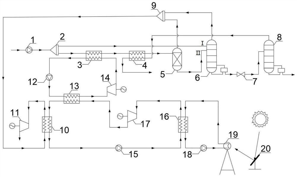
[0026] The present invention will be described in further detail below in conjunction with the accompanying drawings.

[0027] see figure 1 , a LNG light hydrocarbon separation coupled two-stage organic Rankine combined cycle power generation system, including an LNG light hydrocarbon separation system, a concentrating solar heat collection cycle system, a two-stage organic Rankine cycle system and a natural gas direct expansion system;

[0028] The LNG light hydrocarbon separation system includes an LNG pump 1, the outlet side of the working fluid of the LNG pump 1 is connected to the inlet side of the three-way device 2, and the outlet side of the three-way device 2 is divided into two branches, one of which is connected to the outlet side into the feed port 1 of the demethanizer 6, the other outlet side of the three-way device 2 is connected to the cold flow inlet side of the first heat exchanger 3, and the cold flow outlet side of the first heat exchanger 3 is connected to...


PUM


Abstract

A LNG light hydrocarbon separation coupled two-stage organic Rankine combined cycle power generation system, including LNG light hydrocarbon separation system, concentrating solar heat collection cycle system, two-stage organic Rankine cycle system and natural gas direct expansion system; LNG light hydrocarbon separation system The system is used for the recovery of C2+ light hydrocarbon resources; the concentrating solar heat collection cycle system is used for light-to-heat conversion; the two-stage organic Rankine cycle system and natural gas direct expansion system are used for LNG cold energy and medium and low temperature solar energy coupled power generation; Use solar energy as a heat source for two-stage organic Rankine cycle power generation, and store the waste heat discharged from it, and continue to provide heat for the first-stage organic Rankine cycle at night, so that the system can reach a state of continuous power generation and realize the effective recovery of C2+ light hydrocarbon resources. As well as the efficient and complementary utilization of LNG cold energy and solar energy, it has the advantages of reasonable and compact structure, safe and flexible control, high efficiency and energy saving, strong practicability and low cost.

Description

technical field [0001] The invention relates to a complementary utilization system of LNG cold energy and solar energy, in particular to a two-stage organic Rankine combined cycle power generation system coupled with LNG light hydrocarbon separation. Background technique [0002] LNG (liquefied natural gas, liquefied natural gas) needs to be gasified to normal temperature before being supplied to users. LNG will release about 830-860kWh / kg of cold energy during the gasification process. If this part of cold energy can be utilized, it will produce huge economic benefits. The rich C2+ light hydrocarbon components in LNG are very high-quality chemical raw materials, which can be used to produce many petrochemical products with high added value. Using LNG cold energy to separate its own light hydrocarbon components can realize efficient utilization of LNG, but the utilization rate of LNG cold energy is not high. [0003] The organic Rankine cycle using low-boiling point hydroc...

Claims


Application Information

Patent Timeline
Patent Type & Authority Patents(China)
IPC IPC(8): F01K23/02F01K13/00F01K25/10F03G6/06
CPCF01K23/02F01K13/00F01K25/10F03G6/067Y02E10/46
Inventor 潘杰李默翻白俊华唐凌虹李冉刘佳伦翁羽
Owner XI'AN PETROLEUM UNIVERSITY
Learn More