Method for preparing crystalline silicon solar cell electrode

A solar cell and electrode technology, which is applied in circuits, photovoltaic power generation, electrical components, etc., can solve the problems of battery performance degradation, battery performance degradation, and printability degradation, so as to improve battery electrical performance, ensure over-ink performance, and reduce manufacturing costs. low effect

Inactive Publication Date: 2020-08-25
TIANJIN AIKO SOLAR ENERGY TECH CO LTD
View PDF6 Cites 2 Cited by
  • Summary
  • Abstract
  • Description
  • Claims
  • Application Information

AI Technical Summary

Problems solved by technology

[0005] (1) The mesh knot or steel wire at the opening of the screen will form ups and downs on the electrode grid, and the grid line resistance will be higher at the trough of the line. The current advanced screen no-network technology is only by reducing the opening. The proportion of the steel wire increases the opening ratio to reduce the fluctuation of the grid electrode, but it cannot eliminate the peak-valley fluctuation at the top of the longitudinal section of the wire
[0006] ⑵Because the screen is in the process of printing from the lower knife position to the knife receiving position, from the edge of the scraper to the middle position, the force on the whole screen plate is not uniform, so the shape of the formed lines is not uniform. For shading and The influence of resistance is also different, and the unevenness of the electrode grid will cause the loss of light and electricity
[0007] (3) After the paste is repeatedly printed on the screen, the proportion of small molecular resin components that are easy to pass through the screen in the paste gradually decreases, while the proportion of long-chain molecular resin components that are not easy to pass through the screen continues to increase. At the same time, the solvent continues to volatilize. The screen penetration of the slurry is getting worse and worse, and the number of broken grids and virtual printing is gradually increasing, resulting in a decline in battery performance
[0008] (4) The tension and other properties of the screen plate will rapidly decay with the increase of the number of uses, resulting in the worsening of the prepared grid electrode, and the performance of the battery will also decrease with the increase of the number of uses of the screen plate.
[0009] (5) The width of the grid lines formed by screen printing is getting closer and closer to the lower limit, and the requirement for a higher aspect ratio is already at the bottleneck
[0010] (6) A high content of molding resin in the slurry is conducive to the formation of grid lines with a higher width ratio, but at the same time, the printability is reduced and the broken grid will increase. Reducing the resin content can reduce the broken grid, but the printed grid line is easy to collapse and expand. Wide, low gate line aspect ratio
The result of the combined balance of grid aspect ratio and printability is that neither is optimal

Method used


Image

  • Method for preparing crystalline silicon solar cell electrode
  • Method for preparing crystalline silicon solar cell electrode
  • Method for preparing crystalline silicon solar cell electrode

Examples


Embodiment 1

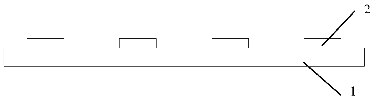
[0035] Such as figure 1 Shown, is a kind of method for preparing crystalline silicon solar cell electrode of the present invention, specifically comprises the following steps:

[0036] S1. Prepare a cured film layer 2 on the position corresponding to each electrode on the silicon wafer substrate 1. The material of the cured film layer 2 is wax. Specifically, the wax is heated and melted by heating the screen printing method, and printed on the silicon wafer substrate. 1 on. The wax is naturally cooled and solidified during the transmission process, forming a solidified film layer 2;

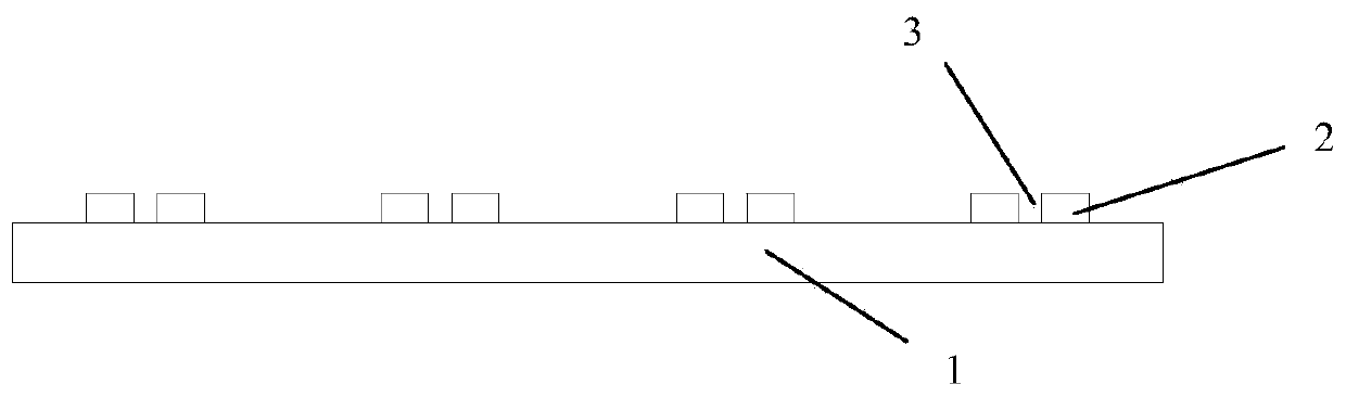
[0037] S2. Use a laser to open a groove 3 on the cured film 2 along the electrode extension direction, the groove 3 penetrates the cured film 2, and the width of the groove 3 is smaller than the width of the cured film 2;

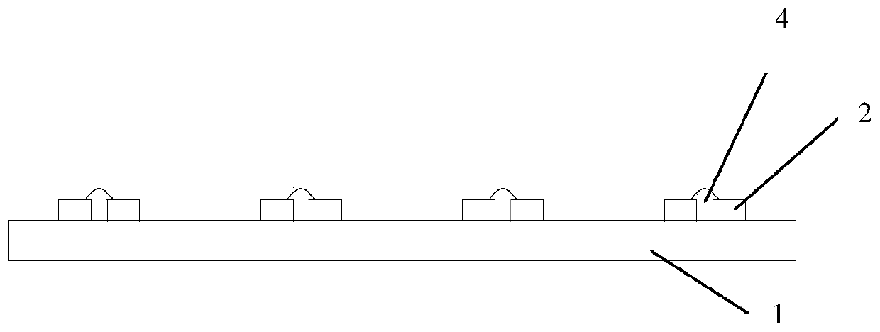
[0038] S3, using the method of screen printing, filling the electrode slurry 4 in the groove 3, the electrode slurry 4 is a low-viscosity slurry, which is a prior art, speci...

Embodiment 2

[0041] A kind of method for preparing crystalline silicon solar cell electrode of the present invention specifically comprises the following steps:

[0042] S1. Prepare a cured film layer at the position corresponding to each electrode on the silicon wafer base. In this embodiment, the material of the cured film layer is UV-cured acrylic resin. Form a layer of cured film;

[0043] S2. Use a laser to open a groove on the cured film layer along the electrode extension direction, the groove penetrates the cured film layer, and the width of the groove is smaller than the width of the cured film layer;

[0044] S3, use the method of screen printing to fill the electrode slurry in the groove, the electrode slurry is a low-viscosity slurry, which is the prior art, specifically the common slurry of Heraeus produced by DuPont , reduce the viscosity to 5~250×10 by adding diluent -3 Pa·s is available. The main function of the wax layer is to support the metal electrode grid lines and ...


PUM

PropertyMeasurementUnit
viscosityaaaaaaaaaa

Abstract

The invention discloses a method for preparing a crystalline silicon solar cell electrode. The method comprises the steps that S1, cured film layers are prepared at the positions, corresponding to allthe electrodes, of a silicon wafer substrate; S2, a groove is formed in the cured film layer in the electrode extending direction, the groove penetrates through the cured film layer, and the width ofthe groove is smaller than that of the cured film layer; S3, the groove is filled with the electrode slurry; and S4, drying and sintering are carried out, the cured film layer is volatilized, the electrode slurry is melted, and through cooling, the electrode slurry is recrystallized to form the electrode. In the process of preparing the electrode, the electrode slurry is supported and blocked bythe cured film layer, the slurry does not collapse or expand, the electrode grid line can be ensured to have a higher depth-to-width ratio, and the electrical performance of the cell is improved; theviscosity of the used electrode slurry can be lower than that of conventionally used slurry, so that the grooves can be filled with the electrode slurry by means of printing or ink jetting and the like, ink passing performance and good flowability are guaranteed, and the electrical performance of the cell is improved.

Description

technical field [0001] The invention relates to solar cell preparation technology, in particular to a method for preparing crystalline silicon solar cell electrodes. Background technique [0002] Photovoltaic energy, as one of the clean energy sources, has achieved tremendous development all over the world. As the main force of photovoltaic energy, crystalline silicon cells have played a pivotal role in the development of photovoltaic energy. At the same time, crystalline silicon solar cells have also gained With rapid development, various new technologies have emerged and been applied, which has continuously promoted the efficiency and cost reduction of photovoltaic power generation. The photovoltaic electricity price has gradually approached the grid parity electricity price. [0003] No matter what kind of battery structure, the metal electrode is the most important part of the indispensable electric current. There are various ways to prepare metal electrodes, such as th...

Claims


Application Information

Patent Timeline
Patent Type & Authority Applications(China)
IPC IPC(8): H01L31/0224H01L31/18
CPCH01L31/022425H01L31/1804Y02E10/547
Inventor 顾生刚夏利鹏刘海金江中强杨二存赵本定杨联赞逯承承
Owner TIANJIN AIKO SOLAR ENERGY TECH CO LTD
Why Eureka
Try Eureka