Laser cladding method for inner wall of hydraulic support oil cylinder

A hydraulic support and laser cladding technology, applied in maintenance and safety accessories, coatings, metal material coating processes, etc., can solve problems such as difficulty in reducing production costs, low material utilization, and inability to realize corners, and achieve a reduction in comprehensive Cost, overall cost reduction, high degree of freedom effect

Active Publication Date: 2020-08-28
SHAANXI TIANYUAN MATERIALS PROTECTION TECH
View PDF12 Cites 2 Cited by
  • Summary
  • Abstract
  • Description
  • Claims
  • Application Information

AI Technical Summary

Problems solved by technology

[0011] The object of the present invention is to provide a laser cladding method for the inner wall of the hydraulic support cylinder. On the basis of adopting a single technology for the laser cladding of the inner wall of the traditional hydraulic support cylinder, the advantages of the two traditional laser cladding technologies for the inner wall of the oil cylinder are absorbed, and the two traditional The combination of laser cladding technology on the inner

Method used


Image

  • Laser cladding method for inner wall of hydraulic support oil cylinder
  • Laser cladding method for inner wall of hydraulic support oil cylinder
  • Laser cladding method for inner wall of hydraulic support oil cylinder

Examples


Embodiment 1

[0054] Below in conjunction with embodiment 1, the present invention is described in further detail.

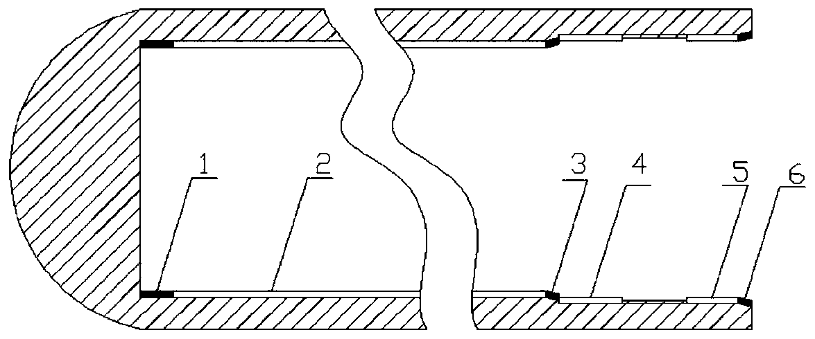
[0055] In this embodiment 1, the laser cladding of the present invention is performed on the inner wall of the 400 type waste hydraulic support oil cylinder (hereinafter referred to as 400 outer cylinder). The material of the oil cylinder outer cylinder is 27SiMn, as shown in the attached figure 1As shown, the inner diameter of the first area 1, the second area 2 and the third area 3 of the inner wall of the cylinder is 400 mm, the inner diameter of the fourth area 4, the fifth area 5 and the sixth area 6 is 420 mm, and the overall depth of the inner hole is 1900 mm. After measurement and calculation, the first area 1 is the bottom corner area with a length of 50mm and an area of ​​0.0628㎡; the second area 2 is an inner wall area with a length of 1550mm and an area of ​​1.9468㎡; the third area 3 and the sixth area 6 As the chamfering structure area, both are chamfering struct...

Embodiment 2

[0073] Below in conjunction with embodiment 2, the present invention is described in further detail.

[0074] In Example 2, laser cladding is carried out on the inner wall of the middle cylinder of the 300-type brand-new hydraulic support cylinder (hereinafter referred to as the 300 middle cylinder) by adopting the solution of the present invention. The material of the middle cylinder is 27SiMn, and the mechanical structure is as attached figure 1 As shown, the inner diameter of the first zone 1, the second zone 2 and the third zone 3 of the cylinder inner wall of the oil cylinder is 300mm, the inner diameter of the fourth zone 4, the fifth zone 5 and the sixth zone 6 is 320mm, and the total inner hole of the middle cylinder Depth 1900mm. After measurement and calculation, the first area, as the bottom corner, has a length of 50mm and an area of ​​0.0471㎡; the second area 2 is an inner wall area with a length of 1550mm and an area of ​​1.4601㎡; the third area 3 and the sixth a...


PUM


Abstract

The invention provides a laser cladding method for the inner wall of a hydraulic support oil cylinder. The laser cladding method comprises the following steps that step 1, defect machining treatment and cleaning treatment are conducted on the inner wall of the hydraulic support oil cylinder before cladding; step 2, laser cladding is conducted on a deep hole bottom end corner area and a chamfer structure area of the inner wall, treated in the first step, of the hydraulic support oil cylinder through an oblique angle coaxial powder feeding laser cladding device, and a cladding layer is formed; step 3, laser cladding is conducted on other inner wall areas, subjected to cladding in the second step, of the hydraulic support oil cylinder through a wide light spot paraxial broadband powder feeding laser cladding device, and a cladding layer is formed; and step 4, finished product aftertreatment machining is conducted on the inner wall, subjected to cladding in the third step, of the hydraulicsupport oil cylinder. According to the laser cladding method, the manner of combining two cladding technologies is adopted for conducting laser cladding treatment on the inner wall of the oil cylinder to be subjected to cladding, meanwhile, the beneficial effects of the wide light spot laser cladding technology and the beneficial effects of the oblique angle coaxial laser cladding technology areconsidered, and the production cost of cladding of the inner wall of the hydraulic support oil cylinder is reduced.

Description

technical field [0001] The invention belongs to the field of advanced manufacturing technology, and in particular relates to a high-efficiency and low-cost laser cladding method for the inner wall of a hydraulic support cylinder. Background technique [0002] As an advanced surface modification technology and additive manufacturing technology, laser cladding technology is usually used in the surface remanufacturing of waste parts and the surface strengthening of new products. It can prepare a metallurgically bonded cladding layer on the surface of parts. While restoring the size of waste parts, it can improve the wear resistance and corrosion resistance of the surface, so that the parts have better performance and longer service life. Therefore, it has been widely used in the surface remanufacturing of various waste parts and various new parts. Surface strengthening. [0003] As a type of equipment with a large number and high value in coal mining equipment, the hydraulic s...

Claims


Application Information

Patent Timeline
IPC IPC(8): C23C24/10B23Q11/10
CPCC23C24/103B23Q11/10Y02P10/25
Inventor 苏成明李建勋张毅赵俊霖白鹏飞
Owner SHAANXI TIANYUAN MATERIALS PROTECTION TECH
Why Eureka
Try Eureka