Distributed soil heat conductivity coefficient testing system and testing method thereof

A technology of thermal conductivity and testing method, which is applied in the field of distributed soil thermal conductivity testing method and its testing system, can solve the problem of obtaining distributed thermal conductivity which has not been proposed, it is difficult to meet the assumption conditions of the hot wire method, and it is difficult to satisfy the thermal conductivity Computing requirements and other issues to achieve the effect of high test efficiency, diversified functions, and long test distance

Active Publication Date: 2020-09-04
NANJING UNIV +1
View PDF10 Cites 7 Cited by
  • Summary
  • Abstract
  • Description
  • Claims
  • Application Information

AI Technical Summary

Problems solved by technology

Although this method has been used in some applications, it has not been proposed to obtain the distributed thermal conductivity
Obviously, the thermal response test method used to obtain other parameters is difficult to meet the assumptions of the hot wire method, so it is difficult to meet the calculation requirements of thermal conductivity

Method used


Image

  • Distributed soil heat conductivity coefficient testing system and testing method thereof
  • Distributed soil heat conductivity coefficient testing system and testing method thereof
  • Distributed soil heat conductivity coefficient testing system and testing method thereof

Examples


Embodiment 1

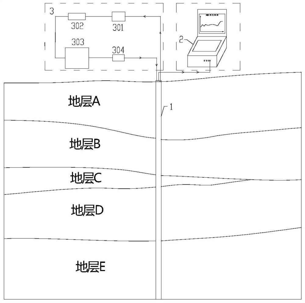
[0077] Take a specific embodiment as an example below to illustrate the specific implementation process and test effect of the present invention, and the installation of the test system is referred to figure 1 .

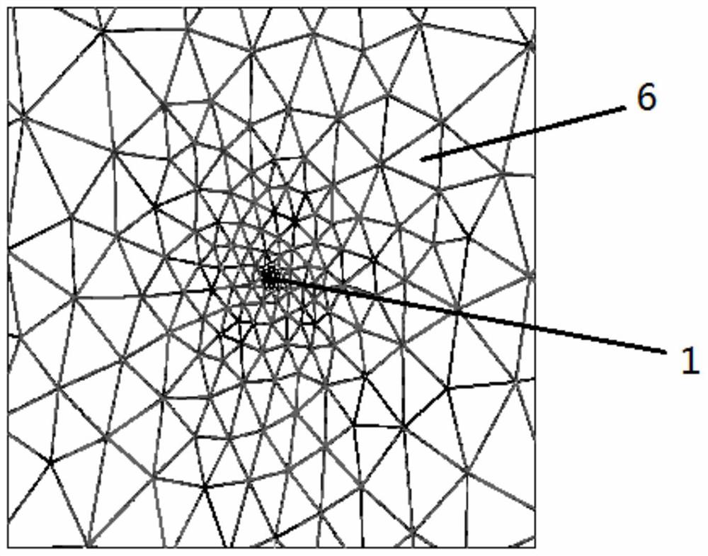
[0078] Step S1, burying the composite optical cable 1 in the soil body 6 to be tested;

[0079] The composite optical cable 1 is respectively connected with the optical signal processing control module 2 and the heating control module 3 to form an optical path and a heating circuit, and the connectivity of the optical path and the heating circuit is tested respectively.

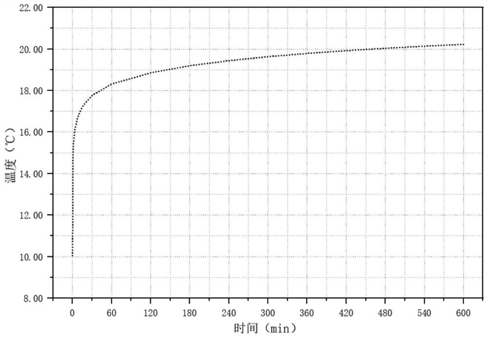
[0080] Step S20, using the optical signal processing control module to collect the initial temperature of the soil to be measured, the collection interval is 0.5min, and the collection time t1≥30min; determine the standard deviation σ of the initial temperature, if the standard deviation σ>0.5 °C, repeat the step S20; if the standard deviation σ≤0.5 °C, store the initial temperature, and execute st...

Embodiment 2

[0096] like Figure 5-6 As shown, take the vertical test embodiment in a specific borehole as an example to illustrate the specific implementation process and test effect of the present invention. The depth of drilling is 95m, and the radius of the borehole is 153mm. The borehole is backfilled with fine sand, and the coupling time is longer than 6 months.

[0097] Step S1, burying the composite optical cable 1 in the soil body 6 to be tested by drilling, the composite optical cable 1 is arranged in a U shape on the wall of the transduction tube 5, which includes a sinking section 11 and a section opposite to the sinking section. The return section 12, the interval between the sinking section and the return section is 3-5cm, and the heating power q per unit length is twice the heating power per unit length of a single composite optical cable. The inner diameter of the transducer tube is 30mm, and the outer diameter is 32mm. It is arranged in the center of the borehole in a dou...


PUM

PropertyMeasurementUnit
thermal conductivityaaaaaaaaaa

Abstract

The invention discloses a distributed soil heat conductivity coefficient testing method and testing system, and the testing method comprises the following steps: burying a composite optical cable in ato-be-tested soil body, wherein the composite optical cable comprises an optical fiber and a thermal resistance material layer wrapping the optical fiber; a heating control module is used for heatingthe to-be-measured soil body through the thermal resistance material layer, and an optical signal processing control module is used for continuously collecting heating temperature data of the stratum; processing the heating temperature data by using an optical signal processing control module, calculating and outputting heat conductivity coefficients of the soil body to be measured at different depths according to a heat conductivity coefficient calculation formula, and drawing a curve graph of the heat conductivity coefficients and the depths. According to the invention, the testing system is small in size, convenient to carry, long in testing distance, capable of monitoring the temperature change of the rock-soil body in a deeper range, high in testing efficiency, small in testing result error and capable of obtaining a refined stratum heat conductivity coefficient within a short testing time.

Description

technical field [0001] The invention relates to the technical field of geological detection, in particular to a distributed soil thermal conductivity test method and a test system thereof. Background technique [0002] The thermal conductivity of rock and soil is a key parameter reflecting the thermal conductivity of rock and soil. On the one hand, obtaining thermal conductivity can serve shallow geothermal energy evaluation, underground engineering, freezing construction or foundation design in freeze-thaw areas, etc. On the other hand, it can also indirectly calculate soil moisture content, groundwater seepage, pollutant transfer, etc. through thermal conductivity parameter. [0003] Methods for obtaining thermal conductivity include indoor experiments and field tests. The indoor test includes the plate method and the hot wire method, and the field test is the transient hot wire method. For the transient hot wire method, a metal wire (hot wire) is inserted into the rock...

Claims


Application Information

Patent Timeline
Patent Type & Authority Applications(China)
IPC IPC(8): G01N25/20
CPCG01N25/20
Inventor 顾凯施斌张博魏广庆向伏林魏壮曹鼎峰
Owner NANJING UNIV
Why Eureka
Try Eureka