Manufacturing forming method of electric arc fuse additive

A technology of additive manufacturing and forming methods, which is applied in the direction of manufacturing tools, additive processing, arc welding equipment, etc., can solve the problems of metal loss at the boundary of structural parts, affect surface forming quality, and affect deposition efficiency, etc., to improve forming Efficiency and quality, improvement of surface forming quality, effect of increasing deposition efficiency

Inactive Publication Date: 2020-09-11
NAT INST CORP OF ADDITIVE MFG XIAN
View PDF6 Cites 1 Cited by
  • Summary
  • Abstract
  • Description
  • Claims
  • Application Information

AI Technical Summary

Problems solved by technology

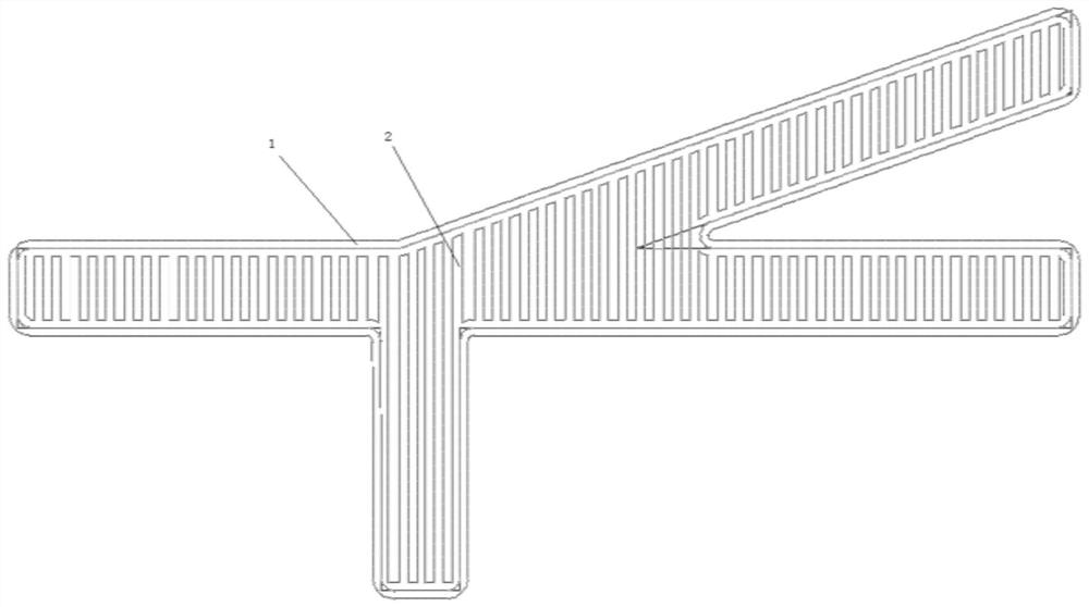
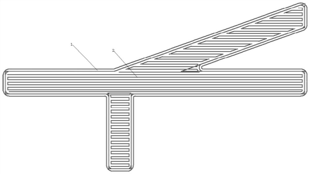
[0003] At present, the heat sources for additive manufacturing of fuses mainly include arcs, electron beams, lasers, etc. Since the high temperature in the process of additively manufacturing fuses is as high as 1700 ° C, materials such as titanium alloys, high-temperature alloys, and high-strength steels are at the boundary of the additive manufacturing process. Droplets are easy to diffuse outside the boundary. With the increase of the deposition layer and number height, the traditional deposition process is easy to cause the collapse caused by the loss of metal at the boundary of the structural part, thus affecting the surface forming quality. At present, the software algorithm of the deposition path is mainly improved , in order to expect the collapse caused by the loss of metal at the boundary of the structure from the reduction of the deposition heat or deposition rate, but it leads to a decrease in the deposition rate and affects the deposition efficiency

Method used


Image

  • Manufacturing forming method of electric arc fuse additive
  • Manufacturing forming method of electric arc fuse additive

Examples


Embodiment

[0032] In the above-mentioned molding method of reducing heat input, the specific method in the deposition process is:

[0033] The first layer: the deposition heat input current is 180A-220A, the voltage is 21V-29V, the internal filling deposition heat input current is: 180-190A, the wire feeding speed is: 1.5m / min-5m / min, and the welding speed is: 0.15 m / min~0.5m / min, ion gas flow rate: 1.2L / min~4L / min; protective gas flow rate: 8L / min~12L / min; interlayer cooling time 0.5min~10min;

[0034] The second layer: deposition heat input current is 175A~210A, wire feeding speed: 1.5m / min~5m / min, welding speed: 0.15m / min~0.5m / min, ion gas flow: 1.2L / min~ 4L / min; protective gas flow: 8L / min~12L / min; interlayer cooling time 0.5min~10min;

[0035] The third layer: profile deposition heat input current is 170A ~ 200A, wire feeding speed: 1.5m / min ~ 5m / min, welding speed: 0.15m / min ~ 0.5m / min, ion gas flow: 1.2L / min ~4L / min; protective gas flow: 8L / min~12L / min; interlayer cooling time 0...


PUM


Abstract

The invention discloses a manufacturing forming method of an electric arc fuse additive. The method comprises the following steps: separating a part to be formed into an inner layer filling area and an outer layer outline along a slice layer, so that a forming filling path of an inner ring and an outer ring is formed, then depositing the inner layer filling area or the outer layer outline according to the inner layer filling area and the outer layer outline of the slice layer, and after the inner layer filling area or outer layer outline deposition is completed, finally, carrying out outer layer outline deposition or inner layer filling area deposition. The forming filling path and interlayer staggered deposition are combined, in the deposition process of each layer, the outer layer outline is deposited firstly, then the inner structure is deposited, or the inner area is deposited firstly, then the outer outline is deposited, thus collapse caused by outflow of metal molten drops at theboundary can be avoided, the surface forming quality is improved, meanwhile, the inner-layer deposition and outer-layer deposition are adopted, so that two-layer deposition cooling is facilitated, and the deposition efficiency is improved.

Description

technical field [0001] The invention belongs to the technical field of plasma fuse additive manufacturing, and in particular relates to an arc fuse additive manufacturing molding method. Background technique [0002] The principle of fuse additive manufacturing is: use drawing software to design the 3D model of parts, and then use "slicing" software to layer and slice according to the structure of the parts, and then generate the corresponding path planning program code, and then use fuse additive The manufacturing method is to pile up layer by layer according to the planned path, and finally form a three-dimensional solid part blank. [0003] At present, the heat sources for additive manufacturing of fuses mainly include arcs, electron beams, lasers, etc. Since the high temperature in the process of additively manufacturing fuses is as high as 1700 ° C, materials such as titanium alloys, high-temperature alloys, and high-strength steels are at the boundary of the additive m...

Claims


Application Information

Patent Timeline
Patent Type & Authority Applications(China)
IPC IPC(8): B23K9/133B23K9/32B33Y10/00
CPCB23K9/133B23K9/32B33Y10/00
Inventor 方学伟许康杨建楠白浩王帅鹏张丽娟赵纪元卢秉恒
Owner NAT INST CORP OF ADDITIVE MFG XIAN
Why Eureka
Try Eureka