Slurry shield muck treatment system and method for synchronous grouting
A muddy water shield and treatment system technology, which is applied in the direction of sustainable waste treatment, solid waste management, climate sustainability, etc., can solve the problems such as difficulty in cutting muck and soil, and achieves convenient follow-up use, low cost, and wide trial range Effect
- Summary
- Abstract
- Description
- Claims
- Application Information
AI Technical Summary
Problems solved by technology
Method used
Image

Examples
Embodiment 1
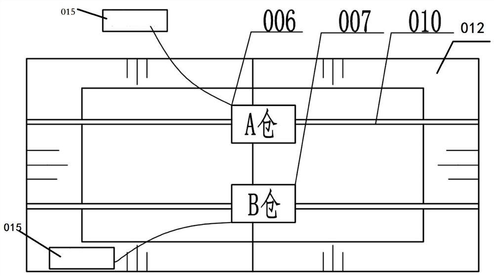
[0040] A slurry treatment system for mud-water shield for synchronous grouting, the treatment system includes a slag collection device, the slag collection device is composed of a left warehouse 008 and a right warehouse 009 to form a mixing bin 012, and the upper part of the mixing bin 012 is equipped with two slideway 010;
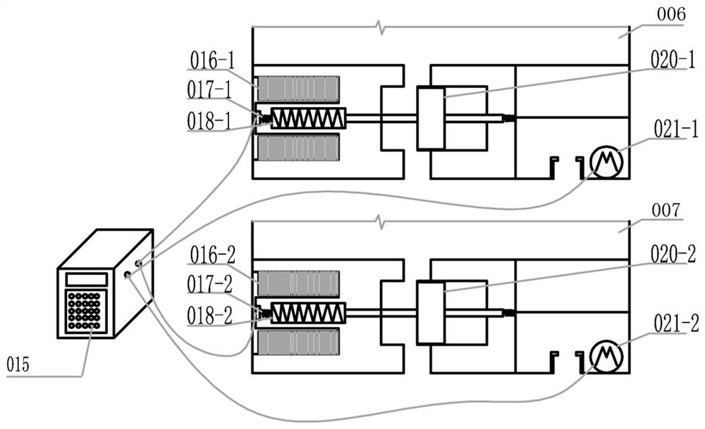
[0041] The two slideways 010 are respectively provided with slidable warehouse A 006 and warehouse B 007, and the bottoms of warehouse A 006 and warehouse B 007 are respectively provided with a first solenoid valve and a second solenoid valve for discharging; The first motor 021-1 and the second motor 021-2 that drive the sliding of the A warehouse 006 and the B warehouse, the first solenoid valve, the second solenoid valve, the first motor 021-1 and the second motor 021-2 and the central processing The output terminal of device 015 is electrically connected.
[0042] The first solenoid valve includes a first coil 016-1, a first iron core 018-1, and a f...
Embodiment 2
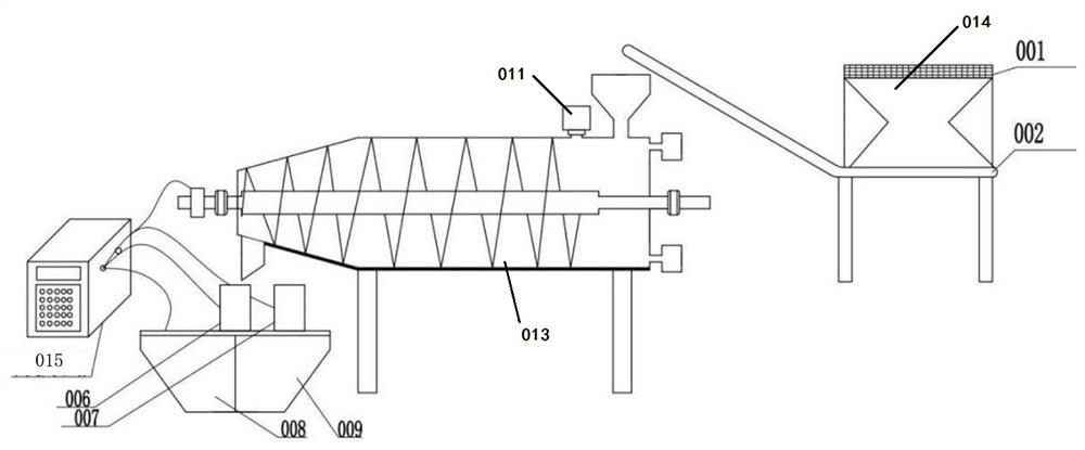
[0054] like figure 1 The flow chart of mud-water shield dregs treatment system for synchronous grouting, including the system composed of the pretreatment of the inlet of the dregs in the front section, the improvement of the dregs in the middle section, and the discharge collection device in the tail. In the first half of the system, the excavated dregs are continuously sent to the vibrating screen 001 through the excavator. When the system senses that the dregs sent into the screen reach 200Kg, the central processing unit starts the vibration of the screen (vibration frequency setting 500r / min), the screened muck can enter the lower belt conveyor 002 through the groove funnel, when the belt senses gravity, the system starts the belt operation and sends the pretreated muck to the improved muck thickening device At the feed port.
[0055] When the slag after the first half of the screening process is completed and sent to the feed port, the system starts and sets the screw sp...
Embodiment 3
[0062] According to above-mentioned embodiment 1, when the qualified slag obtained after the implementation of 2 is applied to the sand source of slurry in the synchronous grouting, the synchronous mortar containing muddy water shield waste slag in each square is calculated by dry basis weight percentage, and the grouting material is stirred Refer to JGJ / T 70-2009 "Basic Performance Test Methods for Building Mortar" for the method and mixer selection; refer to JGJ / T 70-2009 for the apparent density, consistency, loss of consistency over time, and layering degree of the grouting material slurry; note The fluidity and loss of fluidity of the grout material are tested with reference to GB / T50448-2015 "Technical Specifications for Application of Cement-based Grouting Materials"; the test method of bleeding rate refers to the provisions of GB / T 2582-2010 "Prestressed Grouting Agent". The compressive strength of the grouting material is JGJ / T233020-11 made into a 70.7mm×70.7mm×70.7mm...
PUM
| Property | Measurement | Unit |
|---|---|---|
| pore size | aaaaa | aaaaa |
| specific surface area | aaaaa | aaaaa |
| compressive strength | aaaaa | aaaaa |
Abstract
Description
Claims
Application Information
 - R&D
- Intellectual Property
- Life Sciences
- Materials
- Tech Scout
- Unparalleled Data Quality
- Higher Quality Content
- 60% Fewer Hallucinations
Browse by: Latest US Patents, China's latest patents, Technical Efficacy Thesaurus, Application Domain, Technology Topic, Popular Technical Reports.
© 2025 PatSnap. All rights reserved.Legal|Privacy policy|Modern Slavery Act Transparency Statement|Sitemap|About US| Contact US: help@patsnap.com