LNG tank container BOG recovery system and recovery method
A tank container and recovery system technology, applied in the container filling method, container discharge method, packaging, etc., can solve the problems of aggravating the greenhouse effect and environmental pollution, and achieve the effects of high automation level, efficient recycling, and easy monitoring and control
- Summary
- Abstract
- Description
- Claims
- Application Information
AI Technical Summary
Problems solved by technology
Method used
Image
Examples
Embodiment 1
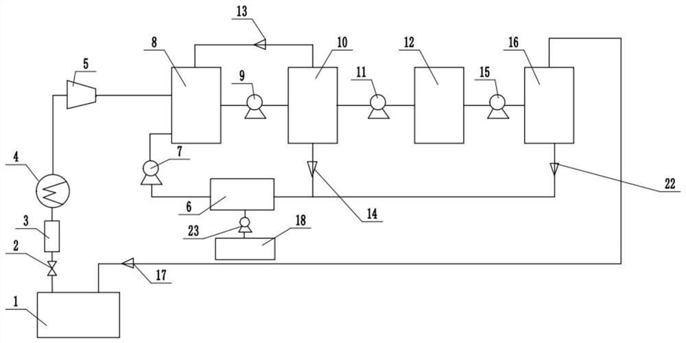
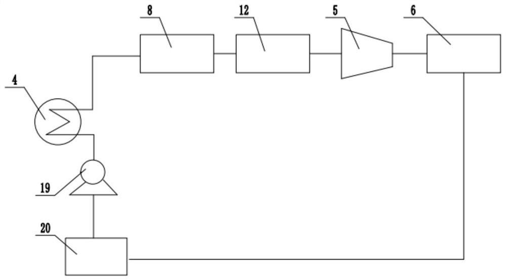
[0046] The present invention provides a BOG recovery system for an LNG tank container, which includes an LNG tank container 1, a hydrate reactor 8 sequentially connected to the LNG tank container 1, a three-phase separator 10, and a hydrate storage tank 12 and hydrate decomposition device 16;
[0047] The gas phase outlet of the LNG tank container 1 is connected to the hydrate reactor 8 through the low-temperature heat exchanger 4 and the compressor 5 in sequence;
[0048] Also includes a water tank 6, one end of the water tank 6 is connected to the hydration reactor 8 through the cryogenic liquid pump 7, and the other end of the water tank 6 is respectively connected to the three-phase separator 10 and the hydrate decomposition device 16, that is, the water tank The other end of 6 is connected in parallel with the three-phase separator 10 and the hydrate decomposition device 16, and the water tank 6 is connected with the additive storage tank 18 through the additive delivery ...
Embodiment 2
[0058] The present invention provides a BOG recovery system for an LNG tank container, which includes an LNG tank container 1, a hydrate reactor 8 sequentially connected to the LNG tank container 1, a three-phase separator 10, and a hydrate storage tank 12 and hydrate decomposition device 16;
[0059] The gas phase outlet of the LNG tank container 1 is connected to the hydrate reactor 8 through the low-temperature heat exchanger 4 and the compressor 5 in sequence;
[0060] Also includes a water tank 6, one end of the water tank 6 is connected to the hydration reactor 8 through the cryogenic liquid pump 7, and the other end of the water tank 6 is respectively connected to the three-phase separator 10 and the hydrate decomposition device 16, that is, the water tank The other end of 6 is connected in parallel with the three-phase separator 10 and the hydrate decomposition device 16, and the water tank 6 is connected with the additive storage tank 18 through the additive delivery ...
Embodiment 3
[0091] The difference between this embodiment and Embodiment 2 is that the liquid phase in the LNG tank container 1 is also connected to the low-temperature heat exchanger 4 , the compressor 5 and the hydrate reactor 8 sequentially through the plunger pump 21 .
[0092] In this embodiment: the BOG overpressure in the gas phase space in the LNG tank container 1 is released through the safety valve 2, and is pressurized and / or transported by the compressor 5 after passing through the flame arrester 3 and the low-temperature heat exchanger 4, and stored in the Additives such as surfactants and nanoparticles in the additive storage tank 18 are mixed with the water in the water tank 6 delivered by the cryogenic liquid pump 7 to form a solution, and the liquid phase of the LNG tank container 1 is delivered by the plunger pump 21, and the liquid phase is transferred through the cryogenic exchange process. Heater 4 enters the hydrate reactor 8 together with the low-temperature natural ...
PUM
 Abstract
Description
Claims
Application Information
 - R&D
- Intellectual Property
- Life Sciences
- Materials
- Tech Scout
- Unparalleled Data Quality
- Higher Quality Content
- 60% Fewer Hallucinations
Browse by: Latest US Patents, China's latest patents, Technical Efficacy Thesaurus, Application Domain, Technology Topic, Popular Technical Reports.
© 2025 PatSnap. All rights reserved.Legal|Privacy policy|Modern Slavery Act Transparency Statement|Sitemap|About US| Contact US: help@patsnap.com


