Drive circuit suitable for parallel connection of SiC MOSFET

A driving circuit and parallel technology, applied in electrical components, high-efficiency power electronic conversion, output power conversion devices, etc., can solve the problems of huge current flowing in SiC MOSFET, the parasitic parameters of the circuit cannot be guaranteed to be completely consistent, and the static current is not balanced. Avoid current imbalance problems, improve electrical performance and durability, and balance the effect of circuit operation

Inactive Publication Date: 2020-09-22
NANTONG UNIVERSITY
View PDF8 Cites 4 Cited by
  • Summary
  • Abstract
  • Description
  • Claims
  • Application Information

AI Technical Summary

Problems solved by technology

In addition, the parasitic parameters of the circuit cannot be guaranteed to be exactly the same
Therefore, when multiple SiC MOSFETs are operated in parallel, there is usually a problem of current imbalance, including the imbalance of dynamic current during the switching process and the imbalance of quiescent current at the turn-on moment.
Due to the existence of unbalanced current, it is easy to make some SiC MOSFETs flow a huge current, causing damage to the device

Method used


Image

  • Drive circuit suitable for parallel connection of SiC MOSFET
  • Drive circuit suitable for parallel connection of SiC MOSFET
  • Drive circuit suitable for parallel connection of SiC MOSFET

Examples


Embodiment Construction

[0023] The following will clearly and completely describe the technical solutions in the embodiments of the present invention with reference to the accompanying drawings in the embodiments of the present invention. Obviously, the described embodiments are only some, not all, embodiments of the present invention. Based on the embodiments of the present invention, all other embodiments obtained by persons of ordinary skill in the art without making creative efforts belong to the protection scope of the present invention.

[0024] In the description of the present invention, it should be noted that the terms "upper", "lower", "inner", "outer", "front end", "rear end", "both ends", "one end", "another end" The orientation or positional relationship indicated by etc. is based on the orientation or positional relationship shown in the drawings, and is only for the convenience of describing the present invention and simplifying the description, rather than indicating or implying that ...


PUM


Abstract

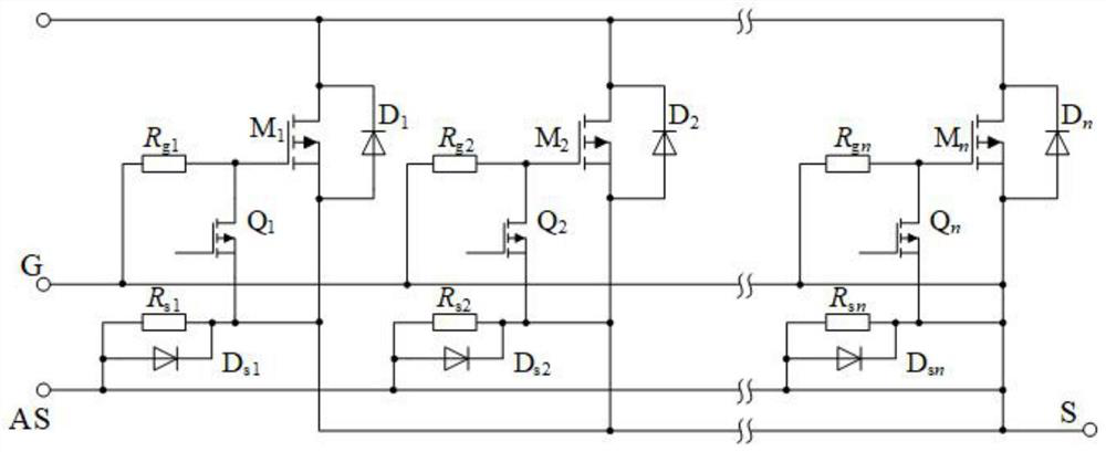
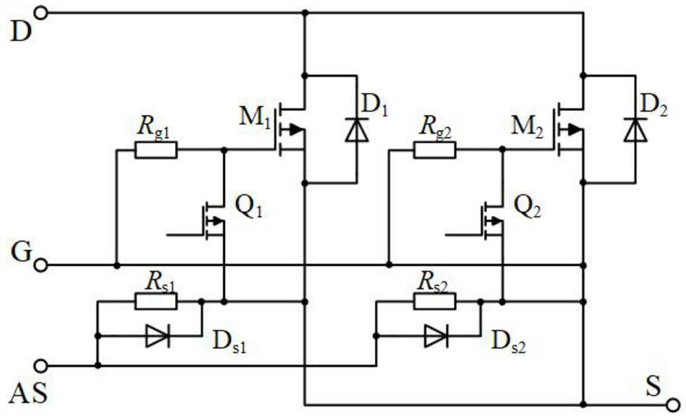
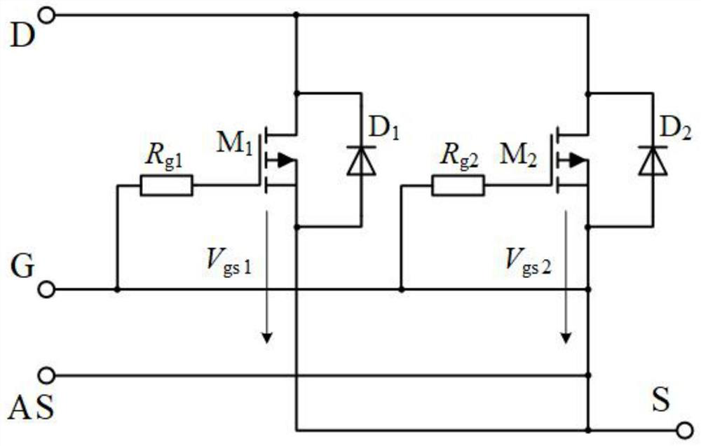
The invention discloses a drive circuit suitable for parallel connection of SiC MOSFETs. The drive circuit comprises a gate resistor Rgx; anauxiliary source electrode resistor Rsx which is provided with a Schottky diode Dsx in parallel connection; and a common low-voltage Si MOSFET tube Qx arranged between the grid electrode and the source electrode. According to the universal parallel SiC MOSFETdriving circuit structure,the number of SiC MOSFETs which can be connected in parallel is not limited. One end of the grid resistor Rgx is connected with the grid electrode of the SiC MOSFET Mx; the drain electrode of the common low-voltage Si MOSFET Qx is connected to the grid electrode of the SiC MOSFET, and the source electrode of the common low-voltage Si MOSFET Qx is connected to the two endsof the source electrode of the SiC MOSFET; one end of the source resistor Rsx is connected with the source of the SiC MOSFET Mx; drain electrodes of all the SiC MOSFETs are connected together to forma common drain electrode end D; and the other end of the gate resistor Rgx is connected to form a common gate terminal G. According to the invention, the problems of unbalanced switching speed of theSiC MOSFETs connected in parallel, non-uniform gate threshold voltage and parallel circulation caused by stray inductance are solved, and the SiC MOSFETs can be effectively protected.

Description

technical field [0001] The invention relates to the technical field of drive circuits, in particular to a drive circuit suitable for parallel connection of SiC MOSFETs. Background technique [0002] With the emergence of wide bandgap semiconductor devices such as SiC MOSFETs, power electronic equipment can work at higher operating voltage, power, power density, switching frequency, and operating temperature, and can achieve smaller volume and loss. Compared with the traditional device Si IGBT, SiC MOSFET can be applied to occasions with higher switching frequency and higher power density, and its performance is significantly better than Si IGBT. However, due to the limitation of process technology, the current resistance value of a single SiC MOSFET device is limited, and it cannot completely replace Si IGBT, and it can only be applied to applications with small current levels. To apply SiC MOSFET devices with low current capacity to high current applications, it is necessa...

Claims


Application Information

Patent Timeline
Patent Type & Authority Applications(China)
IPC IPC(8): H02M1/088
CPCH02M1/088Y02B70/10
Inventor 张雷赵婧琳孙艺鹤任磊杨德健严秋锋
Owner NANTONG UNIVERSITY
Why Eureka
Try Eureka