
An energy-saving straw decomposition machine with automatic control of the distance between grinding discs and its control method

A technology of decomposing machine and moving grinding disc, which is applied in mechanical/thermomechanical pulp, textiles, papermaking, papermaking, etc. It can solve the problems of high power consumption and heavy motor load, and achieve the effects of simple structure design, improved quality and stable current

Active Publication Date: 2022-04-12
北京创源基业自动化控制技术研究所
View PDF8 Cites 0 Cited by
  • Summary
  • Abstract
  • Description
  • Claims
  • Application Information

AI Technical Summary

Problems solved by technology

The motor has a large load and consumes a lot of power

Method used

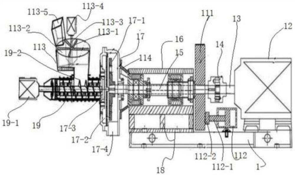

Image

  • An energy-saving straw decomposition machine with automatic control of the distance between grinding discs and its control method
  • An energy-saving straw decomposition machine with automatic control of the distance between grinding discs and its control method
  • An energy-saving straw decomposition machine with automatic control of the distance between grinding discs and its control method

Examples


Embodiment 1

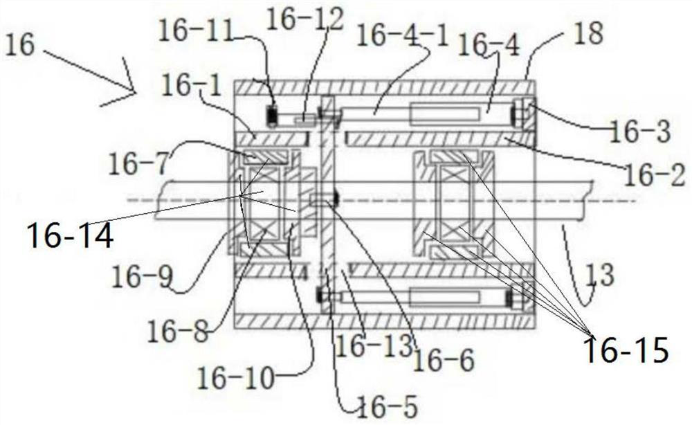
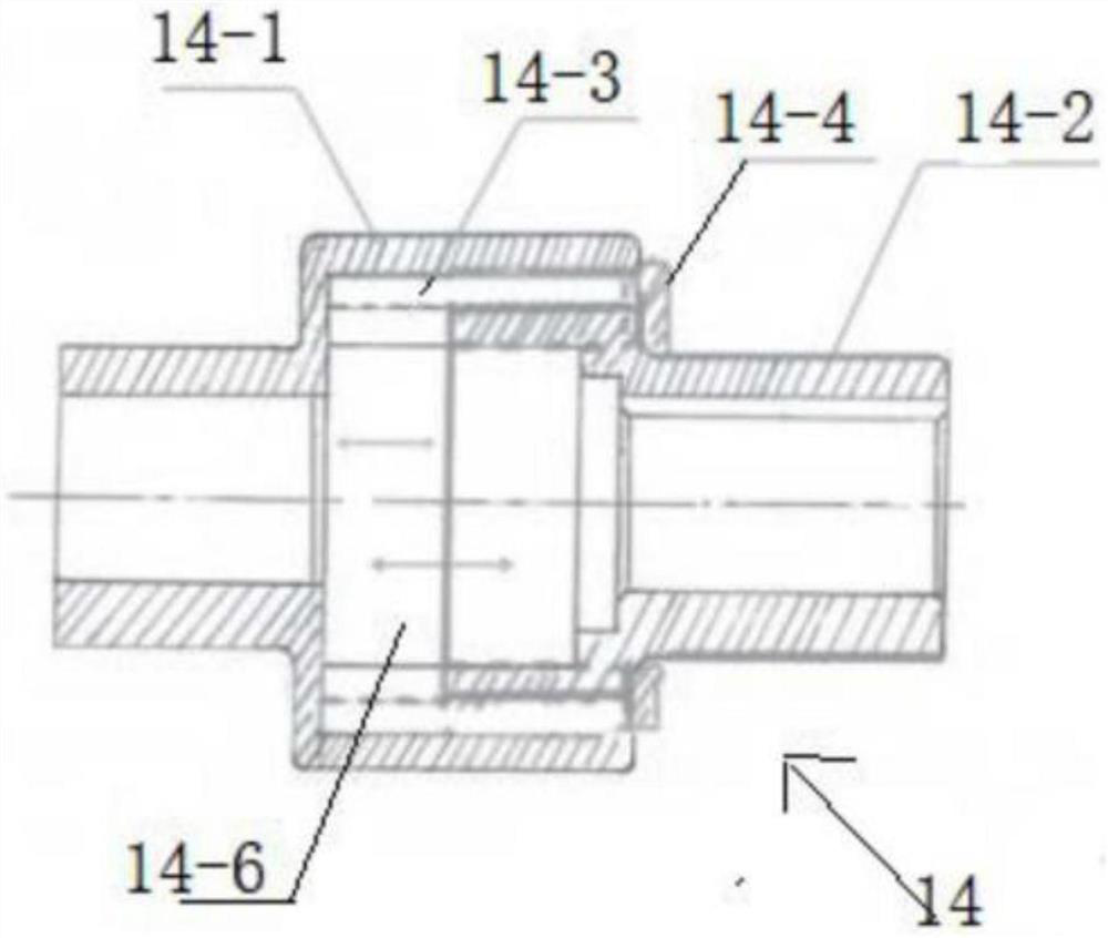
[0058] see figure 1 , figure 2 , image 3 , Figure 4 and Figure 5 , in this embodiment, an energy-saving straw decomposition machine that automatically controls the distance between the grinding discs, including a base 1 for fixing the straw decomposition machine, a main motor 12 fixed at one end of the base 1, and a motor shaft 13 for the main motor 12 It is affixed to the stretchable coupling 14, the stretchable coupling 14 is affixed to one end of the main rotating shaft 15, and the main rotating shaft 15 passes through the fixed seat 16, and the fixed seat 16 is used to support The main rotating shaft 15 in the rotating state, the other end of the main rotating shaft 15 penetrates into the slurry chamber 17 and is fixedly connected with the moving grinding disc 17-1, and the moving grinding disc 17-1 is fixed to the slurry chamber 17 The fixed grinding disc 17-2 inside is opposite, and the slurry after grinding flows out from the slurry outlet 17-4 of the slurry cha...

Embodiment 2

[0079] Referring to Example 1 figure 1 , figure 2 , image 3 , Figure 4 and Figure 5 The difference between the energy-saving straw decomposer of embodiment 2 and embodiment 2 is that the power source equipment of the straw decomposer of embodiment 2 is preferably a cylinder (not shown), and the cylinders are provided with 6 groups. The 6 groups of cylinders are centrally symmetrically arranged on the connected rear plate 16-3, the dial blades 113-1 are set to 3 pieces, the diameter of the feeding funnel 113 is 1 meter, and the front coupling sleeve Twelve circular holes 14-5 are provided at the joints between 14-1 and the rear coupling sleeve 14-2. The inertia wheel 111 is made of a hard non-metal material (such as resin, emery or silicon carbide), and the first hydraulic rod 112-1 is made of a hard non-metal material (such as resin, emery or silicon carbide). a) made. The outer cover and bearing assembly are made of hard non-metallic materials (such as resin, corund...


PUM

PropertyMeasurementUnit
diameteraaaaaaaaaa

Abstract

The invention discloses a straw disintegrating machine, comprising a base, a main motor fixed at one end of the base, a motor main shaft of the main motor being fixedly connected with a stretchable coupling, and the stretchable coupling being fixedly connected with one end of a main rotating shaft . The main rotating shaft passes through the bearing assembly fixed in the bearing fixed seat. The bearing assembly is used to support the main rotating shaft in the rotating state. The other end of the main rotating shaft is fixedly connected with a moving grinding disc; the bearing assembly can be installed in the power unit. Under the action, the main rotating shaft and the moving grinding disc are driven to move axially, and the effect of adjusting the distance between the moving grinding disc and the static grinding disc is achieved; the invention also discloses a method for automatically controlling the grinding disc distance, which can accurately, continuously and automatically adjust the moving grinding disc. The distance from the static grinding disc; both the dynamic grinding disc and the static grinding disc are made of non-metallic materials; the invention also discloses a balanced feeding device and an inertia wheel device for overcoming the resistance of the grinding disc; the straw decomposing machine has the advantages of energy saving and good pulping effect , The advantages of long service life of the grinding disc.

Description

technical field [0001] The invention belongs to the technical field of straw decomposing machines, and in particular relates to an energy-saving straw decomposing machine and a control method for automatically controlling the distance between grinding discs. Background technique [0002] 1. Project Background [0003] Various crops in our country produce about one billion tons of straw every year, and a considerable part has no way out at present. Straw burning pollutes the atmosphere. Crushing and returning to the field will affect the growth of the next crop and produce a large amount of haze gas. A large amount of straw resources are not utilized. The main reason is that there is a lack of technology that can clean, mass, and benefit, and utilize straw. [0004] The applicant began to study the comprehensive utilization of straws in 1999, and innovated a straw fiber decomposition machine. It uses physical methods without adding any chemical preparations to obtain str...

Claims


Application Information

Patent Timeline
Patent Type & Authority Patents(China)
IPC IPC(8): D21B1/14D21H11/12D21H11/08
CPCD21B1/14D21H11/12D21H11/08
Inventor 苏沁阳
Owner 北京创源基业自动化控制技术研究所
Learn More