
Lead particle and lead paste smelting reduction device

A technology of lead paste and lead granules, which is applied in the direction of preheating costs, waste heat treatment, waste collector recycling, etc., can solve the problems of ineffective use of waste heat of flue gas and low thermal efficiency of lead reduction devices, etc.

Inactive Publication Date: 2020-09-29
重庆德能再生资源股份有限公司
View PDF5 Cites 1 Cited by
  • Summary
  • Abstract
  • Description
  • Claims
  • Application Information

AI Technical Summary

Problems solved by technology

[0005] The present invention intends to provide a lead granule and lead paste smelting and reduction device to solve the problems of low thermal efficiency and ineffective use of flue gas waste heat in existing lead reduction devices

Method used


Image

  • Lead particle and lead paste smelting reduction device
  • Lead particle and lead paste smelting reduction device
  • Lead particle and lead paste smelting reduction device

Examples


Embodiment 1

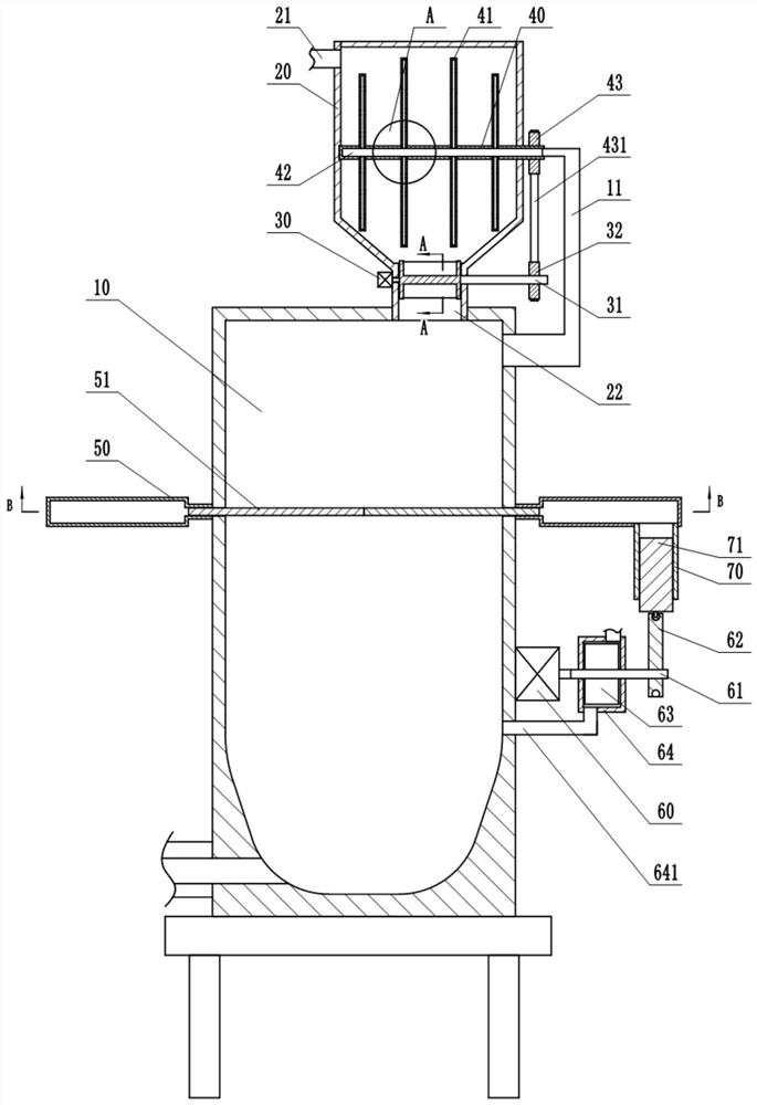
[0033] This embodiment is basically asfigure 1 Shown: lead pellets, lead paste smelting reduction device, including furnace body 10, storage bin 20 and discharge mechanism, storage bin 20 is fixedly installed above the furnace body 10, and the upper part of storage bin 20 is connected with an outlet pipe 21 A discharge channel 22 is connected to the lower part of the storage bin 20 , and the discharge channel 22 communicates with the upper part of the furnace body 10 .

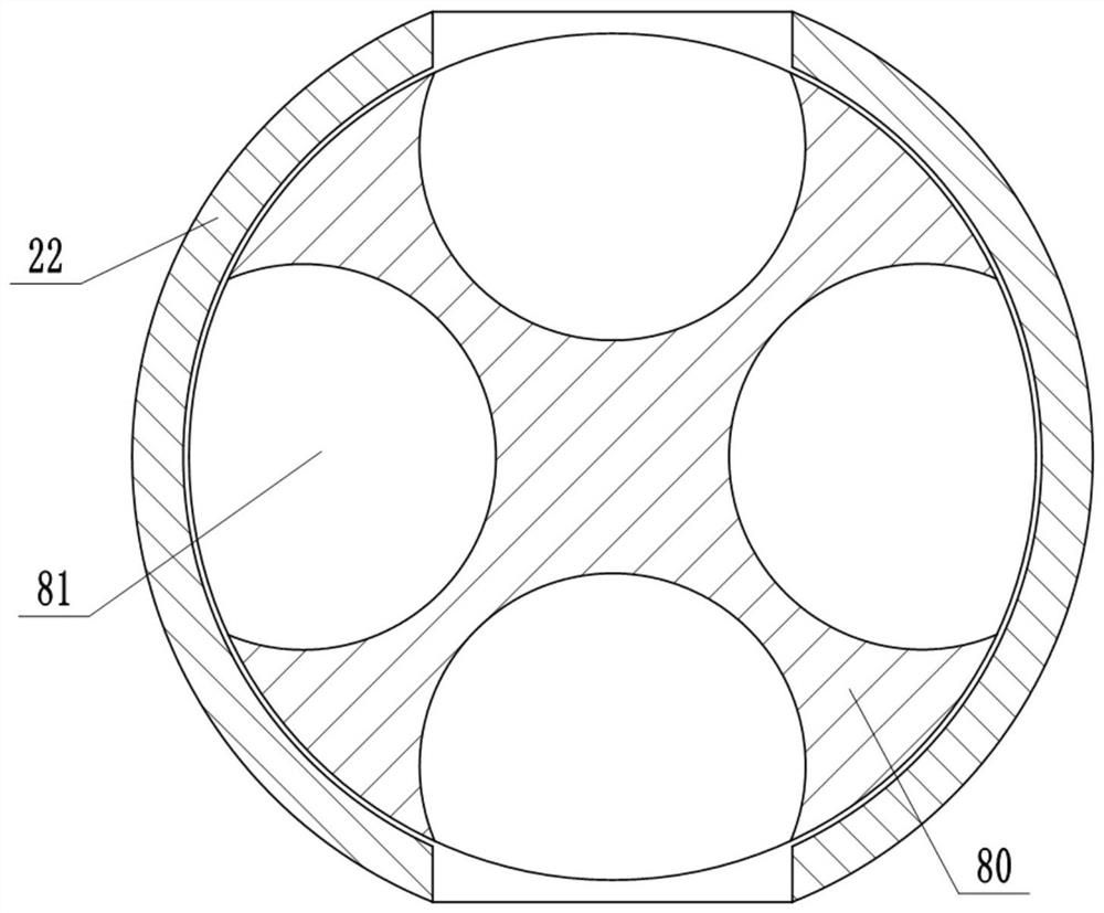
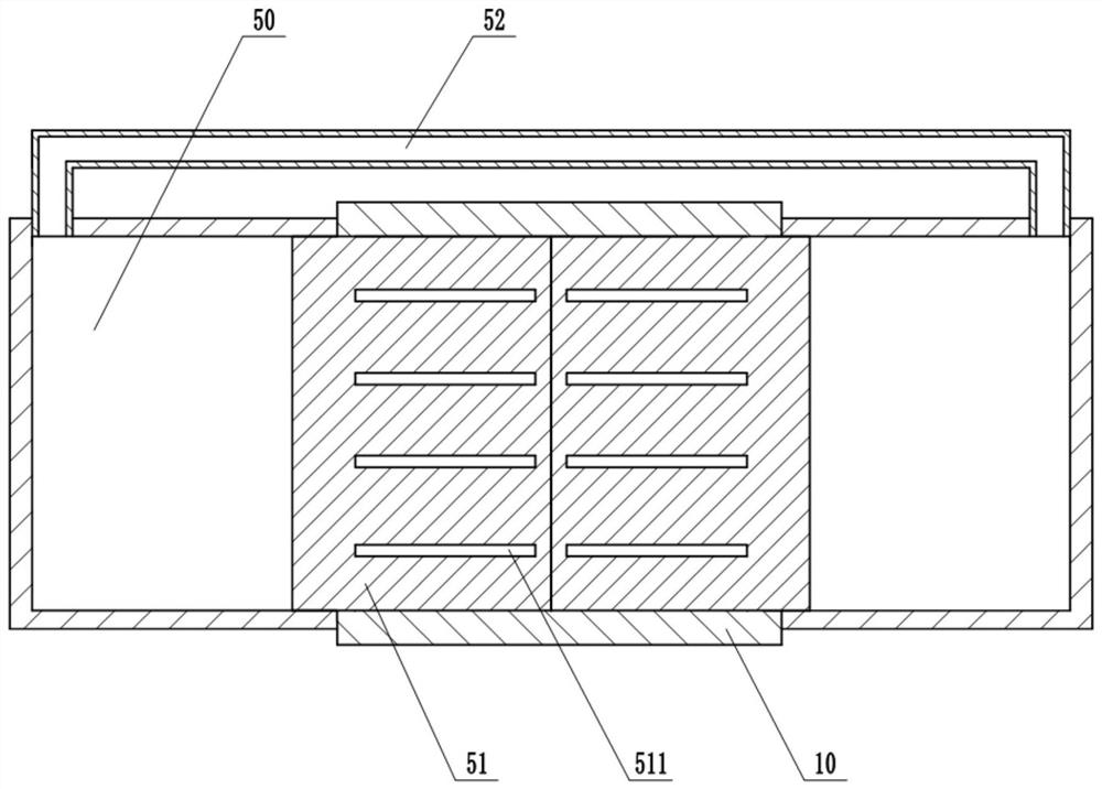
[0034] The discharge mechanism includes a motor 30 fixedly installed on the side wall of the discharge passage 22 and a discharge member rotatably connected in the discharge passage 22. Specifically, the output shaft of the motor 30 is welded on the side wall of the discharge member. A connecting shaft 31 is welded at the center of rotation of the material, and the connecting shaft 31 passes through the side wall of the discharge channel 22 and is located outside the discharge channel 22 . combine figure 2 A...

Embodiment 2

[0041] The difference between the present embodiment and the first embodiment is that the discharge member of the present embodiment is different from the first embodiment, and there is no connecting rod on the plunger 71 of this embodiment, and there is no groove on the cam 62 . combine Figure 5 , Figure 6 As shown, in this embodiment, the discharge member includes a central shaft 90 located in the discharge channel 22 and a plurality of partitions 91 fixed on the central shaft 90, and the plurality of partitions 91 are uniform along the circumference of the central shaft 90. Distributed, a receiving groove is formed between adjacent partitions 91, and the receiving groove can be used for transporting materials. The two opposite side walls of the discharge channel 22 are arc-shaped, and the end of the partition 91 can be in contact with the inner wall of the discharge channel 22 . The connecting cylinder 70 is provided with an elastic member 642 . In this embodiment, the ...


PUM


Abstract

The invention belongs to the technical field of regenerated lead production, and particularly relates to a lead particle and lead paste smelting reduction device. A furnace body, a storage bin and a discharging mechanism are included. The lower portion of the storage bin is connected with a discharging channel, and the discharging channel communicates with the upper portion of the furnace body. The discharging mechanism comprises a discharging piece and a motor driving the discharging piece to rotate. A connecting shaft is arranged at the rotation center position of the discharging piece. Thedischarging piece can block the discharging channel, and in the discharging piece rotation process, materials can be conveyed to the furnace body. A stirring mechanism is arranged in the storage bin and comprises a rotation shaft and a stirring shaft fixed to the rotation shaft. A strip-shaped groove is formed in the stirring shaft. The stirring shaft is provided with a plurality of through holes.A transmission mechanism is arranged between the connecting shaft and the discharging shaft. The furnace body is provided with a flue, and one end of the flue stretches into a cavity of the rotationshaft and is rotationally connected with the rotation shaft. The smelting reduction device in the scheme can effectively recycle heat in high-temperature smoke, and the problems that an existing leadreduction device is low in heat efficiency, and smoke waste heat cannot be effectively utilized are solved.

Description

technical field [0001] The invention belongs to the technical field of secondary lead production, in particular to a smelting and reducing device for lead pellets and lead paste. Background technique [0002] Lead-acid batteries have stable working voltage, wide range of operating temperature and operating current, can charge and discharge hundreds of cycles, good storage performance (especially suitable for dry charging storage), and low cost, so they are widely used. With the mass production of waste lead-acid batteries, the recycling of waste lead-acid batteries is getting more and more attention. One is that the discarding of waste lead-acid batteries will cause serious pollution to the environment; the other is that due to the sharp rise in the price of lead, the recycling of lead has attracted much attention. [0003] At present, metallurgical equipment such as reverberatory furnaces, rotary kilns, and cupolas are mainly used for the smelting and recovery of lead in w...

Claims


Application Information

Patent Timeline
IPC IPC(8): F27B14/00F27B14/16F27B14/08F27D3/00F27D13/00F27D17/00F27D7/02H01M10/54C22B7/00C22B13/02
CPCC22B7/001C22B13/025F27B14/00F27B14/08F27B14/0806F27B2014/085F27D3/0025F27D7/02F27D13/002F27D17/004F27D2003/0083F27D2007/023F27M2001/017F27M2003/13F27M2003/165H01M10/54Y02W30/84Y02P10/20Y02P10/25
Inventor 伍中钢
Owner 重庆德能再生资源股份有限公司
Learn More