
Micro-fluidic chip for detecting micro-pollutants

A microfluidic chip and pollutant technology, applied in fluid controllers, laboratory containers, laboratory utensils, etc., can solve the problems of cumbersome and time-consuming detection processes, inability to detect real-time, and inability to carry around, and achieve a simple structure. , low cost, detection effect without interference

Inactive Publication Date: 2020-10-09
TIANJIN UNIV
View PDF7 Cites 2 Cited by
  • Summary
  • Abstract
  • Description
  • Claims
  • Application Information

AI Technical Summary

Problems solved by technology

[0003] The current environmental pollution detection equipment has many inconveniences: ①Most of the equipment is too bulky to carry around, and the detection requires manual extraction of samples from a specific location
②The detection time and frequency are artificially limited, so real-time detection is impossible
③ The detection process is cumbersome and time-consuming

Method used


Image

  • Micro-fluidic chip for detecting micro-pollutants
  • Micro-fluidic chip for detecting micro-pollutants
  • Micro-fluidic chip for detecting micro-pollutants

Examples


Embodiment Construction

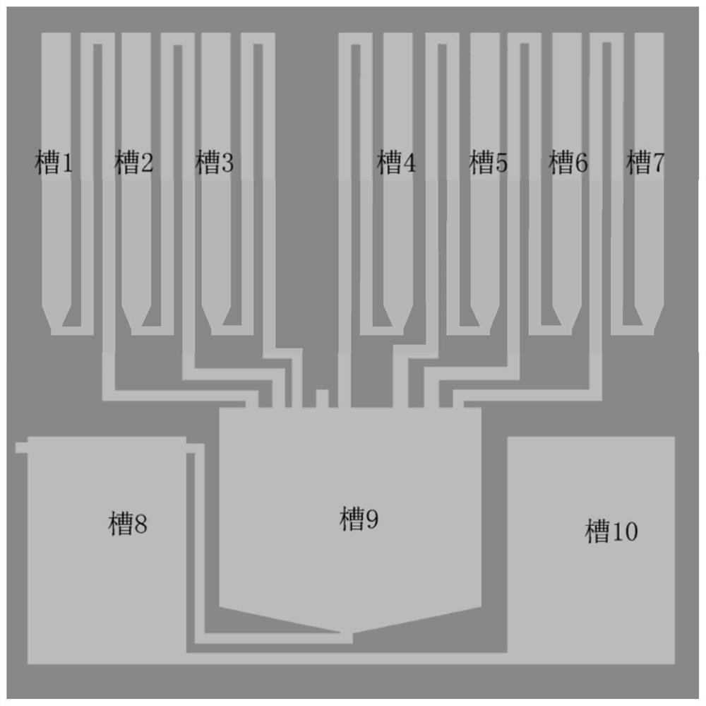
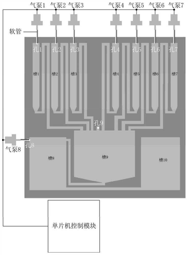
[0012] The specific implementation manner of the present invention will be described in detail below in conjunction with the accompanying drawings and preferred embodiments. like Figure 1-Figure 2 As shown, a microfluidic chip for detecting micro-pollutants uses two acrylic plates to form a sealed groove for storing liquids and mixing reactions. The acrylic plate has good weather resistance, acid and alkali resistance, and long life , Strong impact resistance and many other advantages. Tank 1 is DNA, slot 2 is 30nm gold nanoparticles, slot 3 is 2-naphthol, slot 4 is tris(2-carboxyethyl)phosphine hydrochloride (TCEP), slot 5 is phosphate buffered saline (PBS ), the groove 6 is sodium chloride (NaCl), and the groove 7 is the analyte (such as mercury ion).

[0013] like image 3 As shown, at first, the gold nanoparticles in the tank 2 are blown into the reaction tank by the air pump 2, then the 2-naphthylthiol in the tank 3 is blown into the reaction tank 9 by the air pump 3,...


PUM


Abstract

The invention relates to the technical field of single-chip microcomputers, in particular to a micro-fluidic chip for detecting micro-pollutants, which is characterized by comprising a first acrylic plate and a second acrylic plate, nine engraved grooves are formed in the first acrylic plate and used for storing detection liquid and providing detection space, the first groove to the seventh grooveare used for storing detected objects and objects to be detected, the eighth groove is used for storing waste liquid, and the ninth groove is used for reacting. The device is small, exquisite, portable, simple in structure, low in cost, high in stability, long in service lifetime and free of interference to detection.

Description

technical field [0001] The invention relates to the technical field of single-chip microcomputers, in particular to a microfluidic chip for detecting micro-pollutants. Background technique [0002] In recent years, with the development of industry, the phenomenon of environmental pollution caused by human activities has become more and more serious. There are many sources of heavy pollution. Heavy metals in coal will pollute the air system after burning, illegal discharge of untreated industrial wastewater will pollute rivers, paint on the surface of ships will peel off and fall into the sea due to the accumulation of time, and It is the leakage of a large amount of oil caused by the accidents of some cargo ships and the rupture of the pipeline of the offshore oil drilling platform, which will cause a large amount of heavy metal pollutants to flow into the ocean, causing serious pollution. These pollutants will enter the body of organisms and accumulate, and finally enter t...

Claims


Application Information

Patent Timeline
Patent Type & Authority Applications(China)
IPC IPC(8): B01L3/00
CPCB01L3/5027B01L2400/0487
Inventor 邹强雷志明
Owner TIANJIN UNIV
Learn More