
Energy field assisted intelligent multi-point forming method and system for amorphous alloy parts

An amorphous alloy, multi-point forming technology, applied in computer-aided design, metal processing equipment, instruments, etc., can solve the problems of multiple forming, limited industrial application, easy crystallization and oxidation of amorphous alloys, and achieve coordination. Overall control effect

Active Publication Date: 2020-10-09
HUAZHONG UNIV OF SCI & TECH +1
View PDF7 Cites 5 Cited by
  • Summary
  • Abstract
  • Description
  • Claims
  • Application Information

AI Technical Summary

Problems solved by technology

[0003] However, the traditional forming method needs to process corresponding large-scale forming tooling. For curved surface parts, the tooling is more complicated and the processing cost is extremely high.
When it is necessary to form micro-parts or microstructures with extreme dimensions (<1mm), the forming is difficult and may require multiple formings, and the amorphous alloy is prone to crystallization and oxidation during the forming process, and relaxation brittleness is inevitable
The room temperature brittleness of amorphous alloy materials makes it a great safety hazard in the actual service process
Therefore, the existing forming technology is difficult to realize the shape-controlled collaborative manufacturing of high-performance complex amorphous alloy parts, which greatly limits its industrial application.

Method used


Image

  • Energy field assisted intelligent multi-point forming method and system for amorphous alloy parts
  • Energy field assisted intelligent multi-point forming method and system for amorphous alloy parts
  • Energy field assisted intelligent multi-point forming method and system for amorphous alloy parts

Examples


Embodiment 1

[0094] The target amorphous alloy part is a typical large three-dimensional curved thin-walled part with local bosses, and the material is Zr 55 Cu 30 Ni 5 al 10 Amorphous alloy, the blank is a slab prepared by continuous casting and rolling technology, with a thickness of 3mm. When the traditional plate is deep-drawn to form a local boss, the boss is prone to deep-drawing cracks due to uneven deformation. Pre-brittleness. Moreover, when the force is applied to the boss, it is a stress concentration area, which requires high comprehensive performance of the material. Traditional forming technology is difficult to achieve the shape-property collaborative manufacturing of target amorphous alloy parts. This embodiment carries out multi-point forming to this part according to the following method:

[0095] (1) Digital model extraction and geometric division: perform three-dimensional scanning on the target amorphous alloy part to obtain the shape profile information of the t...

Embodiment 2

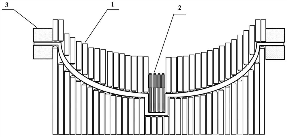
[0119] The target amorphous alloy part and material composition are the same as those in Example 1. Figure 5 Shown is a device schematic diagram of a local electromagnetic field-assisted multi-point forming method for amorphous alloy parts based on the present invention, including 1-multi-point forming unit, 8-electromagnetic field-assisted forming unit, 3-flexible edge-holding unit, etc. The forming steps are the same as in Example 1. Image 6 Shown is a schematic diagram of the electromagnetic field assisted forming system, including 9-electromagnetic coil, 10-electromagnetic excitation power supply. According to the energy field-assisted intelligent multi-point forming method of the present invention, a reasonably distributed electromagnetic field and thermal field are constructed inside the part, and the electromagnetic excitation power supply 10 is turned on before forming, and a 60 Hz power frequency alternating current is passed through the electromagnetic coil 9 to ge...

Embodiment 3

[0121] The target amorphous alloy part and material composition are the same as those in Example 1. Figure 7 Shown is a device schematic diagram of a local electric field-assisted multi-point forming method for amorphous alloy parts based on the present invention, including 1-multi-point forming unit, 11-electric field-assisted forming unit, and 3-flexible edge-holding unit. The forming steps are the same as in Example 1. According to the energy field-assisted intelligent multi-point forming method of the present invention, a reasonably distributed current field and thermal field are constructed inside the part, and a pulse current is locally passed to the amorphous alloy slab before forming, the frequency is 80kHz, the amplitude is 60A, and the duty cycle is 20%. The material relies on self-resistance to generate Joule heat, and at the same time, based on the electroplastic effect, the deformation resistance of the amorphous alloy sheet is significantly reduced, realizing r...


PUM

PropertyMeasurementUnit
currentaaaaaaaaaa
diameteraaaaaaaaaa
diameteraaaaaaaaaa

Abstract

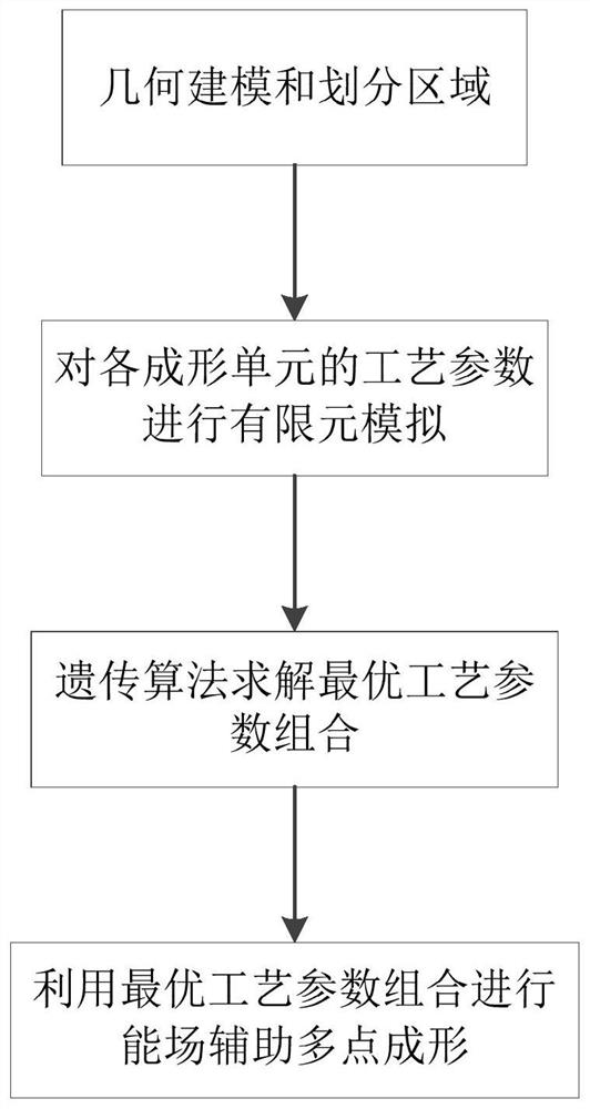
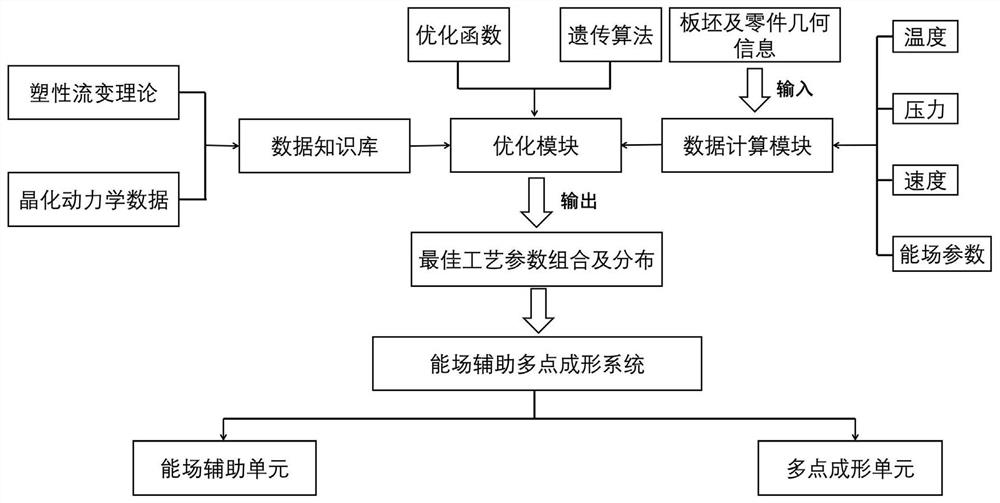
The invention belongs to the field of amorphous alloy flexible forming, and particularly relates to an energy field auxiliary intelligent multi-point forming method and system for amorphous alloy parts. The method comprises the steps of firstly, dividing a plate blank into a plurality of forming areas according to geometric profile information of a target amorphous alloy part and the size information of the plate blank; giving forming process parameters including an energy field to each forming area, forming field distribution in the part, performing finite element simulation of the forming process on the amorphous alloy part, then conducting optimization on a data sample through a genetic control algorithm, and obtaining a process parameter combination, namely optimal field distribution,with the optimal effect for different forming areas; and forming the target amorphous alloy part by adopting a multi-point forming process under the obtained optimal field distribution. The field distribution is formed in the part, the integral forming of the part is coordinated, the shape cooperation intelligent manufacturing of a amorphous alloy complex part can be achieved, the production costis reduced, and the product quality is improved.

Description

technical field [0001] The invention belongs to the field of flexible forming of amorphous alloys, and more specifically relates to an energy field-assisted intelligent multi-point forming method and system for amorphous alloy parts. Background technique [0002] At present, the forming and manufacturing of some large-scale aerospace equipment, such as vehicles, satellites, spaceships, and deep space probes, is constantly developing in the direction of lightweight, integrated, complex, and high-performance. It is increasingly difficult to process key components of high-end equipment such as the heat exchange system and turbine case of hypersonic aircraft engines, the micro-thermal control system of satellite steam chambers, and the micro-grooved drag-reducing structure on the surface of large aircraft. How to realize the collaborative integrated manufacturing of large complex parts with local microstructural features is an important issue in modern high-end manufacturing. M...

Claims


Application Information

Patent Timeline
Patent Type & Authority Applications(China)
IPC IPC(8): G06F30/23G06F30/27G06N3/00B21D26/00B21D26/14B23K26/00G06F119/08G06F119/14
CPCG06F30/23G06F30/27G06N3/006B21D26/14B21D26/00B23K26/00G06F2119/08G06F2119/14
Inventor 龚攀丁华平王新云邓磊金俊松张茂
Owner HUAZHONG UNIV OF SCI & TECH
Learn More