Light emitting device and capacitor

A technology for light-emitting devices and capacitors, applied in the field of capacitors, can solve the problem that distance resolution cannot be fully ensured, and achieve the effect of reducing parasitic inductance

Active Publication Date: 2020-10-13
MURATA MFG CO LTD
View PDF7 Cites 0 Cited by
  • Summary
  • Abstract
  • Description
  • Claims
  • Application Information

AI Technical Summary

Problems solved by technology

Therefore, there is a problem that the on-time width of the output light from the light-emitting device is limited to a value larger than several ns, and the distance resolution cannot be sufficiently ensured.

Method used


Image

  • Light emitting device and capacitor
  • Light emitting device and capacitor
  • Light emitting device and capacitor

Examples


Embodiment approach 1

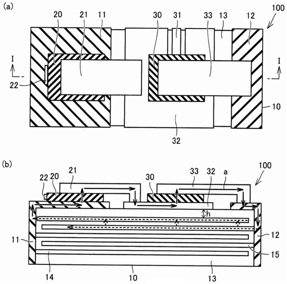
[0038] Hereinafter, the light emitting device according to Embodiment 1 of the present invention will be described with reference to the drawings. figure 1 It is a schematic diagram for explaining the configuration of the light emitting device 100 according to Embodiment 1 of the present invention. also, figure 1 (a) shows a plan view of the light emitting device 100 viewed from the outer surface of the capacitor 10 on which the solid light emitting element 20 is placed, figure 1 (b) is a cross-sectional view on the II plane of the light emitting device 100 .

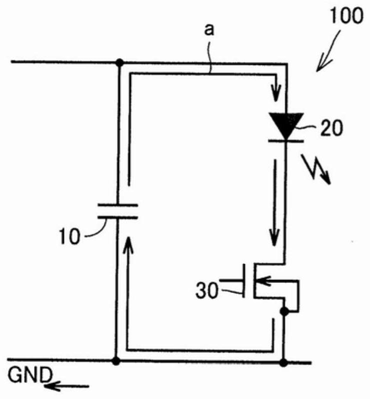
[0039] figure 1 The illustrated light emitting device 100 includes a capacitor 10 , a solid light emitting element 20 mounted on the outer surface of the capacitor 10 , and a semiconductor switch 30 . The capacitor 10 is a capacitor for power supply and is composed of a laminated ceramic capacitor. Therefore, the capacitor 10 is alternately laminated with a plurality of internal electrodes 14 , 15 for obtaining elec...

Embodiment approach 2

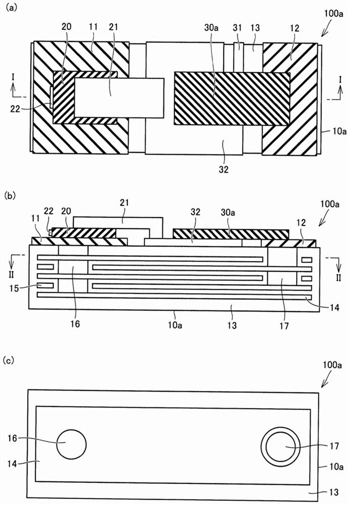
[0053] In the light emitting device 100 according to Embodiment 1, as figure 1 As shown in (b), the external electrodes 11 and 12 are formed at respective ends of the laminated body, and the size of the current loop a is restricted by the external dimensions of the capacitor 10 . Therefore, in Embodiment 2 of the present invention, the capacitor has a structure in which the external electrodes and the internal electrodes are electrically connected using via-hole conductors. image 3 It is a schematic diagram for explaining the structure of the light-emitting device 100a according to Embodiment 2 of the present invention. also, image 3 (a) shows a plan view of the light-emitting device 100a viewed from the outer surface of the capacitor 10a on which the solid-state light-emitting element 20 is placed, image 3 (b) shows a sectional view of the II plane of the light emitting device 100a, image 3 (c) is a cross-sectional view on the II-II plane of the light emitting device 1...

Embodiment approach 3

[0063] In the light-emitting device 100 according to Embodiment 1, the configuration including the capacitor 10 , the solid-state light-emitting element 20 mounted on the outer surface of the capacitor 10 , and the semiconductor switch 30 has been described. However, the elements mounted on the outer surface of the capacitor are not limited to solid light emitting elements and semiconductor switches. Therefore, in Embodiment 3 of the present invention, a configuration in which elements other than the solid-state light-emitting element and the semiconductor switch are placed on the outer surface of the capacitor will be described.

[0064] Figure 4 It is a schematic diagram for explaining the structure of the light-emitting device 100b according to Embodiment 3 of the present invention. also, Figure 4 (a) shows a plan view of the light-emitting device 100b viewed from the outer surface of the capacitor 10a on which the solid-state light-emitting element 20 is placed, Figu...


PUM

PropertyMeasurementUnit
thicknessaaaaaaaaaa
thicknessaaaaaaaaaa
thicknessaaaaaaaaaa

Abstract

Provided is a light emitting device which can achieve short pulsing of light that the device outputs. This light emitting device (100) includes: a capacitor (10); one or more solid state light emitting elements (20) that emit light by having power supplied from the capacitor (10); and a semiconductor switch (30) that controls the supply of power from the capacitor (10) to the solid state light emitting elements (20). The capacitor (10) has a connection electrode (32) which has the solid state light emitting elements (20) mounted on an outer surface thereof, has the semiconductor switch (30) mounted on the outer surface thereof or provided therein, and is for connecting the solid state light emitting elements (20) to the semiconductor switch (30) in series between external electrodes (11),(12).

Description

technical field [0001] The present invention relates to a light-emitting device including one or more solid-state light-emitting elements, and a capacitor capable of mounting one or more solid-state light-emitting elements. Background technique [0002] In recent years, there are cases where LiDAR (Light Detection and Ranging: light detection and ranging) is used in automotive systems, weather observation systems, and the like. LiDAR includes a light emitting device including a laser diode, a semiconductor switch, a clamp diode, and a capacitor for power supply as described in Non-Patent Document 1. [0003] The driving mode of the light emitting device includes a capacitor discharge mode and a switch control mode. In a light-emitting device employing a capacitive discharge method, light having a pulse width is generated from a laser diode by resonance between a parasitic inductance and a capacitor for power supply. On the other hand, in a light-emitting device employing a...

Claims


Application Information

Patent Timeline
Patent Type & Authority Applications(China)
IPC IPC(8): H01L33/00H01G4/33H01G4/40H01S5/022H01S5/0239H05B44/00
CPCH01G4/40H01G4/33H01L25/167H05B45/30H01S5/0239H05B45/40H01G4/30H01S5/042H05B44/00
Inventor 泷本直美松冈高广串间贵仁大原达也安藤翔太中野浩之
Owner MURATA MFG CO LTD
Why Eureka
Try Eureka