Protein enrichment detection device based on light-operated fluid transportation and magnetic control sample separation

A detection device and protein technology, applied in the field of microfluidics, can solve problems such as hindering the miniaturization development of microfluidic devices, low reaction efficiency, waste of samples, etc., and achieve portable protein detection, increase control accuracy, and reduce volume. Effect

Active Publication Date: 2020-10-16
FUDAN UNIV
View PDF9 Cites 5 Cited by
  • Summary
  • Abstract
  • Description
  • Claims
  • Application Information

AI Technical Summary

Problems solved by technology

However, due to the traditional microfluidic system driven by a syringe pump, the fluid movement state is laminar flow, and the mixing between liquid phases is mainly carried out by diffusion, and the reaction efficiency is low, so the detection time is relatively long
Moreover, the carrying capacity of solid particles in the laminar flow system is poor. When introducing magnetic nanoparticles to achieve protein sample capture and enrichment, it is necessary to design a special pipeline structure or introduce a micro-stirrer to ensure the transportation and resuspension of the particles. operate
This increases the complexity of the system design, hinders the miniaturization of the entire microfluidic device, and also reduces the stability of the system.
On the other hand, the liquid sample in the pump-driven microfluidic system is a continuous-phase fluid, and the sample often needs to fill the entire microfluidic chip channel and external pipelines to complete the control, and the proportion of the actual sample used for detection is often very small. Less, which will lead to sample waste to a certain extent, which is limited in the application of detection of precious samples and trace samples

Method used


Image

  • Protein enrichment detection device based on light-operated fluid transportation and magnetic control sample separation
  • Protein enrichment detection device based on light-operated fluid transportation and magnetic control sample separation
  • Protein enrichment detection device based on light-operated fluid transportation and magnetic control sample separation

Examples


Embodiment 1

[0103] Single enrichment and detection of high concentration Avidin protein

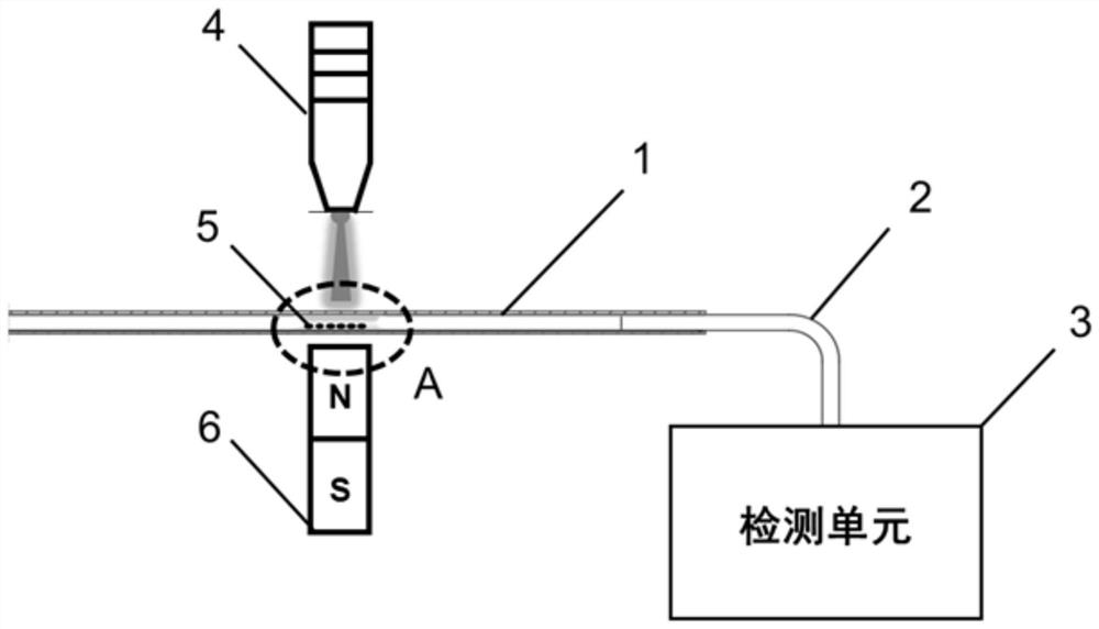
[0104] 1. Inject 5 μL of magnetic nanoparticle solution of surface-modified Biotin molecules at a concentration of 0.5 mg / mL into the optofluidic microtube actuator 1. After the optically controlled particle solution moves to the designated position, a magnetic field is applied to fix the magnetic nanoparticles to form a magnetic field. Nanoparticle capture zone 5. Then the light-controlled supernatant is separated from the magnetic nanoparticle capture zone 5 .

[0105] 2. Inject 5 μL of the Avidin sample to be detected into the optofluidic microtube actuator 1, and after the optically controlled sample to be detected reaches the magnetic nanoparticle capture zone 5, the magnetic field is removed, and the optically controlled solution reciprocates near the magnetic nanoparticle capture zone 5 , resuspend the magnetic nanoparticles, and continue the reciprocating stirring motion for 10 minutes (the ...

Embodiment 2

[0108] Multiple enrichment and detection of low concentration Avidin protein

[0109] 1. Inject 5 μL of magnetic nanoparticle solution of surface-modified Biotin molecules at a concentration of 0.5 mg / mL into the optofluidic microtube actuator 1. After the optically controlled particle solution moves to the designated position, a magnetic field is applied to fix the magnetic nanoparticles to form a magnetic field. Nanoparticle capture zone 5. Then the light-controlled supernatant is separated from the magnetic nanoparticle capture zone 5 .

[0110] 2. Inject 5 μL of the Avidin sample (lower concentration) to be detected into the optofluidic microtube actuator 1. After the light-controlled sample to be detected reaches the magnetic nanoparticle capture zone 5, the magnetic field is removed, and the light-controlled solution is captured by the magnetic nanoparticles. Reciprocate around belt 5 to resuspend the magnetic nanoparticles, and continue to reciprocate and stir for 10 m...

Embodiment 3

[0114] Multiple enrichment and detection of C-reactive protein

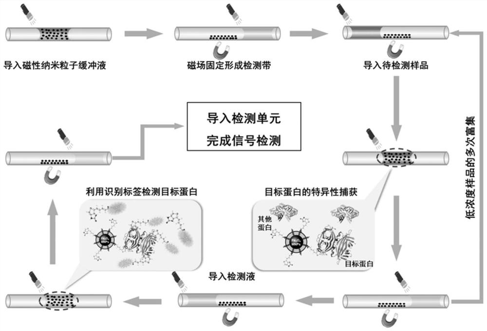
[0115] 1. Introduce particles and fix the capture band: Introduce 5 μL of the magnetic nanoparticle solution of the surface-modified C-reactive protein primary antibody with a concentration of 0.5 mg / mL into the optofluidic microtube actuator 1, move to the designated position, and apply a magnetic field to fix it. Live MNPs to form magnetic nanoparticle trapping strips 5 . The light control particle supernatant is separated from the magnetic nanoparticle capture zone 5 .

[0116] 2. Capture and separation of C-reactive protein samples: import 5 μL of C-reactive protein samples to be detected, light-control the samples to be detected to reach the particle capture zone, remove the magnetic field, light-control the reciprocating motion of the solution, resuspend MNPs, and continue to reciprocate 10min (the reciprocating cycle is 10s), during this process, the C-reactive protein primary antibody on the surface of M...


PUM

PropertyMeasurementUnit
thicknessaaaaaaaaaa
thicknessaaaaaaaaaa
diameteraaaaaaaaaa

Abstract

The invention relates to a protein enrichment detection device based on light-operated fluid transportation and magnetic control sample separation. The interior of an optical flow control micro-tube actuator is used for accommodating magnetic nanoparticles, a to-be-detected liquid sample and a detection liquid and is a place for capturing the target protein of magnetic nano particles and reactionbetween the target protein and detection liquid. An electromagnetic control device is arranged in the middle of the exterior of the optical flow control micro-tube actuator, and exertion and cancellation of a magnetic field are achieved by controlling on-off of a power supply; a control light source is arranged above the outer part of the optical flow control micro-tube actuator and is used for driving liquid in the optical flow control micro-tube actuator to finish directional movement; the detection tube is connected with one end of the optical flow control micro-tube actuator, and the optical detection instrument is used for optical detection of liquid in the detection tube. Compared with the prior art, non-contact control can be achieved, portable protein detection can be truly achieved, and meanwhile the risk that a sample is polluted is effectively avoided.

Description

technical field [0001] The invention relates to the field of microfluidic technology, in particular to a protein enrichment detection device based on optically controlled fluid transport and magnetically controlled sample separation. Background technique [0002] The accurate detection of protein (especially some marker proteins, such as avidin, hemoglobin, C-reactive protein, etc.) has important application prospects and market value in the fields of food safety, clinical medicine, and biology. The protein detection in the microfluidic system can integrate the complex operation and analysis process of the laboratory on a chip of more than ten square centimeters, which has the advantages of less sample consumption and easy operation. However, due to the traditional microfluidic system driven by a syringe pump, the fluid movement state is laminar flow, and the mixing between liquid phases is mainly carried out by diffusion, and the reaction efficiency is low, so the detection...

Claims


Application Information

Patent Timeline
Patent Type & Authority Applications(China)
IPC IPC(8): B01L3/00G01N21/64
CPCB01L3/502761B01L2300/0819B01L2400/043G01N21/6486
Inventor 竺翀宇俞燕蕾鲁遥
Owner FUDAN UNIV
Why Eureka
Try Eureka