
Wind-heating two-phase flow device and method

A phase flow and wind power technology, which is applied in the field of two-phase flow devices induced by wind power, can solve the problems of high equipment cost, wear of the rotating shaft, and attenuation of solid material properties, and achieve high conversion efficiency

Active Publication Date: 2020-10-30
XI AN JIAOTONG UNIV
View PDF14 Cites 0 Cited by
  • Summary
  • Abstract
  • Description
  • Claims
  • Application Information

AI Technical Summary

Problems solved by technology

The first wind heating method is to generate wind power first, and then heat the electric energy through the resistance wire. This method belongs to indirect heating, and the efficiency of converting wind energy into heat energy is not high.
The second wind heating method is to use a wind turbine to drive an air compressor to compress the air and then release heat. The principle of this method is to use the expansion of gas to release heat, and the efficiency of converting wind energy into heat energy is not high.
The third wind heating method is to drive the agitator to rotate at a high speed by the wind turbine and stir the liquid to heat. The principle of this method is to use the friction between the agitator and the liquid to generate heat, and the efficiency of converting wind energy into heat energy is relatively high, but The agitator rotates at a high speed in the liquid for a long time, which is easy to cause the wear of the rotating shaft and cause vibration
The fourth wind heating method is to use wind force to rub solid materials to generate heat. This method has a relatively high efficiency of converting wind energy into heat energy, but the friction of solid materials will inevitably cause wear of the materials, and long-term friction will cause the properties of solid materials to attenuate.
The fifth wind heating method is to use the wind to drive the hydraulic pump, so that the hydraulic oil is sprayed from the small hole at high speed. In the process, the heat is generated through friction and impact, and the wind energy is converted into heat energy. Transmission principle, high equipment cost and difficult operation

Method used


Image

  • Wind-heating two-phase flow device and method
  • Wind-heating two-phase flow device and method
  • Wind-heating two-phase flow device and method

Examples


Embodiment

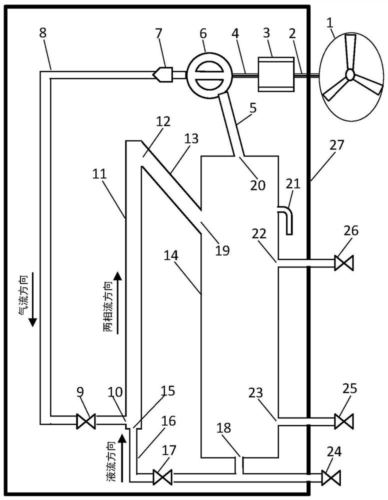
[0073] In this embodiment, the two-phase flow heat pipe 11 is a vertical pipe (sinθ=1) with a length of 2 m and an inner diameter of 0.04 m. The liquid is water, density ρ L =998kg·m -3 , constant pressure specific heat C pL =4200J·kg -1 ·℃ -1 ;The gas is air, density ρ G =1.3kg·m -3 , constant pressure specific heat C pG =1005J·kg -1 ·℃ -1 ; Make the liquid delivery valve 25 and the liquid-repelling valve 24 remain closed, open the replenishment valve 26, and inject 10 liters (0.01m 3 ), and then open the liquid regulating valve 17 to form a liquid column with a height of 0.9m in the two-phase flow heat pipe 11. By adjusting the gas flow rate and liquid flow rate, a slug flow with a gas-liquid ratio of S=100 is formed to generate a high-intensity flow friction effect, convert the mechanical energy of wind force into heat energy, and calculate the liquid heat absorption rate η L = 0.97.

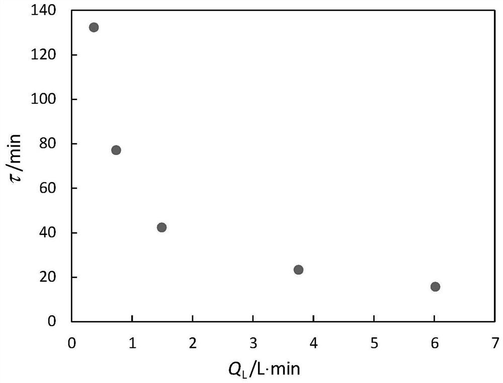
[0074] figure 2 The required time τ and water flow Q are given when heating ...


PUM


Abstract

The invention discloses a wind-heating two-phase flow device and method. The device employs the high-intensity flow friction effect of a vertical pipe (or inclined pipe) gas-liquid two-phase slug flowunder the condition of a large gas-liquid ratio, converts the mechanical energy of wind power into heat energy, and achieves wind heating; and main body components of the device comprise a wind powerimpeller, a transmission, a movable scroll compressor disc, a fixed scroll compressor disc, a two-phase flow heating pipe and a gas-liquid separator, and auxiliary components comprise a connecting pipe and a valve. The wind power impeller and the transmission are connected with the movable scroll compressor disc and the static scroll compressor disc through shafts, replace a motor of a scroll compressor to drive the movable and static scroll compressor discs, and pressurize gas through wind power. The pressurized gas enters the two-phase flow heating pipe to form gas-liquid two-phase slug flow with a large gas-liquid ratio together with liquid in the two-phase flow heating pipe, wind energy is converted into heat energy through the high-strength friction effect, and a wind heating way isexpanded.

Description

technical field [0001] The invention belongs to the technical field of wind energy utilization, in particular to a two-phase flow device and method for heating by wind. Background technique [0002] Wind energy is a renewable and clean energy, and the effective use of wind energy is a hot spot in energy utilization. my country has huge wind energy reserves. It is estimated that the available wind energy on land is about 250,000 MW, and the available wind energy in sea areas is about 750,000 MW. The monsoon caused by the earth's rotation from west to east, wind energy can last for several months in some areas, and has the characteristics of continuous use during day and night, which has its advantages compared with solar energy that can only be used during the day. Relying on wind turbines to convert wind energy into electrical energy is the most common form of wind energy utilization, and wind heating is another form of wind energy utilization. Wind heating technology conv...

Claims


Application Information

Patent Timeline
IPC IPC(8): F03D9/28F03D9/18F03D9/22F03D80/00
CPCF03D9/28F03D9/18F03D9/22F03D80/00Y02E10/72Y02E70/30
Inventor 刘磊黄娜
Owner XI AN JIAOTONG UNIV
Learn More