
DLC coating process

A coating and process technology, applied in the field of DLC coating technology, can solve the problems of insufficient effect, insufficient ionization rate, low deposition rate, etc., and achieve the effects of lowering temperature, increasing ionization rate, and fast deposition rate

Inactive Publication Date: 2020-11-13
东莞市普拉提纳米科技有限公司
View PDF0 Cites 6 Cited by
  • Summary
  • Abstract
  • Description
  • Claims
  • Application Information

AI Technical Summary

Problems solved by technology

[0002] "DLC" is the abbreviation of the word "DIAMOND-LIKE CARBON" in English. DLC is a substance composed of carbon elements, similar in nature to diamonds, and has a structure of graphite atoms. Diamond-like film DLC is a non- Crystalline film, due to its high hardness and high elastic modulus, low friction coefficient, wear resistance and good vacuum tribological properties, is very suitable as a wear-resistant coating, DLC film has good anti-adhesion, especially It is for copper and aluminum, so DLC is widely used in copper and aluminum processing tools, molds, and friction parts. The common PECVD equipment in the market has a slow deposition rate of DLC. During the deposition process, the gas is on the furnace wall and Discharge between transfers, the discharge space is very large, the ionization rate is not high enough, and the deposition rate is low. If the deposition rate is to be increased, a larger power supply is required, and the investment in equipment costs and use costs is greater. Some The equipment uses an auxiliary anode to increase the ionization rate of the discharge, but the auxiliary anode has the same potential as the furnace body and is installed close to the furnace wall, so its effect is not obvious enough; in view of these defects, it is necessary to design a DLC coating process

Method used


Image

  • DLC coating process
  • DLC coating process
  • DLC coating process

Examples


Embodiment Construction

[0033] The following will clearly and completely describe the technical solutions in the embodiments of the present invention with reference to the accompanying drawings in the embodiments of the present invention. Obviously, the described embodiments are only some, not all, embodiments of the present invention. Based on the embodiments of the present invention, all other embodiments obtained by persons of ordinary skill in the art without making creative efforts belong to the protection scope of the present invention.

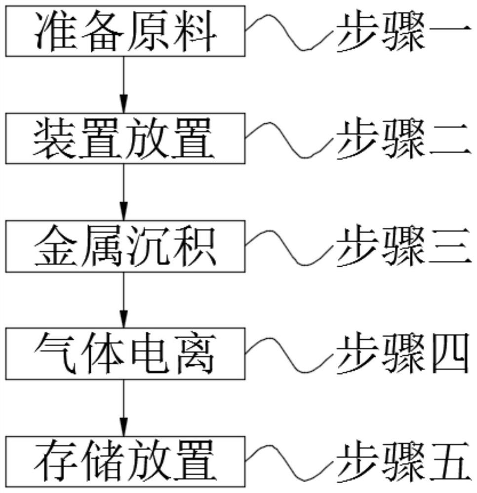
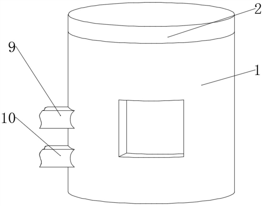
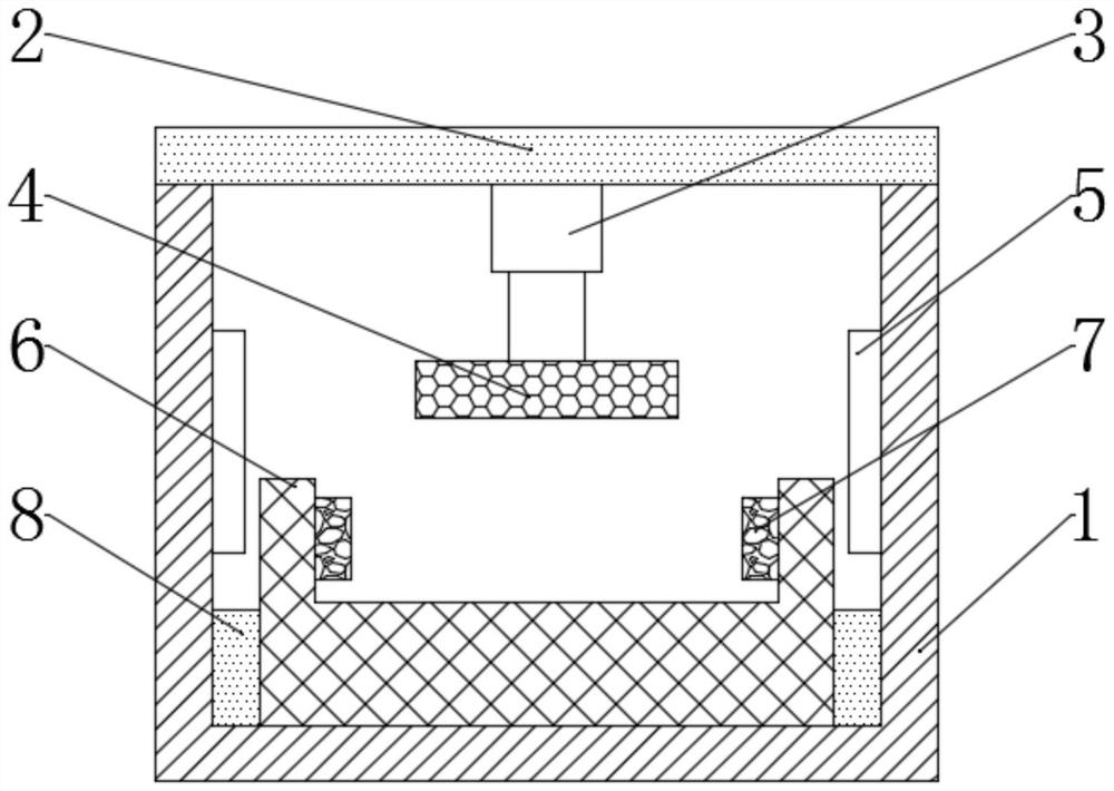
[0034] see Figure 1-3 , the present invention provides a technical solution: a DLC coating process, including step 1, preparing raw materials; step 2, device placement; step 3, metal deposition; step 4, gas ionization; step 5, storage placement;

[0035] Wherein in above-mentioned step one, preparing raw material comprises the following steps:

[0036] 1) Manually detect the required DLC coating materials, and purchase metal target materials according to the...


PUM


Abstract

The invention discloses a DLC coating process which comprises the following steps: step I, preparing raw materials; step II, placing a device; step III, performing metal deposition; step IV, performing gas ionization; and step V, storing and placing, wherein in the step 1, a needed DLC coating material is manually detected, and a metal target material is purchased according to the needed DLC coating material. The DLC coating process has functions of PVD and PECVD, the process equipment is equipped with a magnetic-control sputtering target needed for PVD coating and a discharge electrode neededfor PECVD gas coating as well as a magnetic field coil; the process equipment can realize the DLC coating process at a low temperature; meanwhile, the problem that a carbon film layer needs PECVD while DLC priming needs magnetic-control sputtering, and carbon-containing gas can be split at a lower temperature. The process equipment is high in deposition rate; a way of combining electromagnetic fields generated by the coil with a central auxiliary anode is adopted, and a high-power pulse power supply is assisted, so that an ionization rate of carbon-containing gas is increased, and a deposition rate of the carbon layer is increased.

Description

technical field [0001] The invention relates to the technical field of DLC coating, in particular to a DLC coating process. Background technique [0002] "DLC" is the abbreviation of the word "DIAMOND-LIKE CARBON" in English. DLC is a substance composed of carbon elements, similar in nature to diamonds, and has a structure of graphite atoms. Diamond-like film DLC is a non- Crystalline film, due to its high hardness and high elastic modulus, low friction coefficient, wear resistance and good vacuum tribological properties, is very suitable as a wear-resistant coating, DLC film has good anti-adhesion, especially It is for copper and aluminum, so DLC is widely used in copper and aluminum processing tools, molds, and friction parts. The common PECVD equipment in the market has a slow deposition rate of DLC. During the deposition process, the gas is on the furnace wall and Discharge between transfers, the discharge space is very large, the ionization rate is not high enough, and...

Claims


Application Information

Patent Timeline
Patent Type & Authority Applications(China)
IPC IPC(8): C23C14/35C23C14/14C23C16/26C23C16/02
CPCC23C14/35C23C14/14C23C16/26C23C16/0281
Inventor 刘成斌黄明章
Owner 东莞市普拉提纳米科技有限公司
Learn More