
Organic electroluminescent compound based on phenazine-thiophene-dicyanogen and application

An organic light-emitting layer and luminescent technology, applied in organic chemistry, light-emitting materials, circuits, etc., to reduce production costs and improve efficiency

Active Publication Date: 2020-11-17
山西穿越光电科技有限责任公司
View PDF7 Cites 5 Cited by
  • Summary
  • Abstract
  • Description
  • Claims
  • Application Information

AI Technical Summary

Problems solved by technology

In the past few years, great efforts have been made and some progress has been made in the design and synthesis of thermally activated delayed fluorescent materials emitting red light, but there are few materials with both high efficiency and positive color. Therefore, It is particularly urgent to develop new efficient and stable red-light thermally activated delayed fluorescence OLED materials

Method used


Image

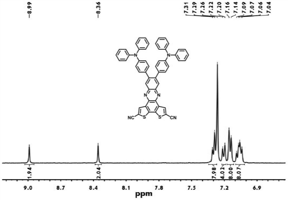
  • Organic electroluminescent compound based on phenazine-thiophene-dicyanogen and application
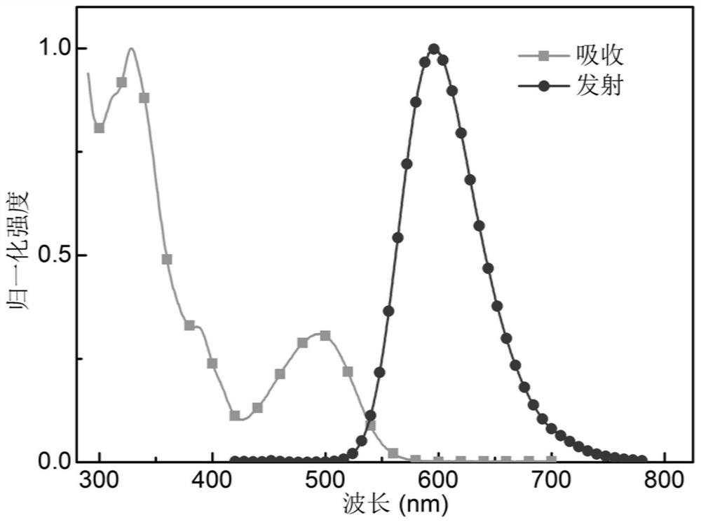
  • Organic electroluminescent compound based on phenazine-thiophene-dicyanogen and application
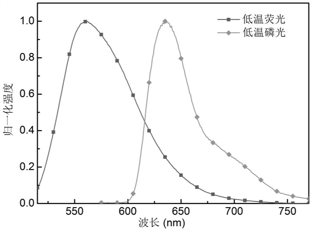
  • Organic electroluminescent compound based on phenazine-thiophene-dicyanogen and application

Examples


Embodiment 3

[0065] Embodiment 3 organic electroluminescence device

[0066] The present invention also provides an organic electroluminescent device prepared by a thermally activated delayed fluorescent material based on the above-mentioned phenazine-thiophene-dicyano planar system, which consists of an anode 1, a hole injection layer 2, The hole transport layer 3, the electron blocking layer 4, the organic light-emitting layer 5, the electron transport layer 6 and the cathode 7 are composed.

[0067] Wherein, the organic light-emitting layer 5 is formed by doping the compound shown in formula 2-5 prepared in Example 1 of the present invention into the host material, and the doping ratios are 10wt.%, 15wt.% and 20wt.%. "Doping ratio" refers to the mass fraction of the compound represented by formula 2-5 in the total weight of the organic light-emitting layer.

[0068] The manufacturing method of the above organic electroluminescent device is prepared by a conventional method. Specifical...

Embodiment 4

[0079] This embodiment provides an organic electroluminescent device, the structure of which is the same as that in Embodiment 3, except that the organic light-emitting layer 5 is doped with the compound shown in Formula 2-6 prepared in Embodiment 2 of the present invention Formed in the host material, its doping ratio is 5wt.%, 10wt.% and 15wt.%.

[0080] The three organic electroluminescent devices OLED4-OLED6 provided in this example use CBP as the host material. The materials and thicknesses of the prepared devices are as follows:

[0081] OLED4: ITO / HAT-CN (10nm) / TAPC (40nm) / TCTA (10nm) / CBP:5wt% compound (20nm) / B4PyMPM (50nm) / Liq (2nm) / Al (120nm) shown in formula 2-6 );

[0082] OLED5: ITO / HAT-CN (10nm) / TAPC (40nm) / TCTA (10nm) / CBP:10wt% compound shown in formula 2-6 (20nm) / B4PyMPM (50nm) / Liq (2nm) / Al (120nm );

[0083] OLED6: ITO / HAT-CN(10nm) / TAPC(40nm) / TCTA(10nm) / CBP:15wt% compound (20nm) / B4PyMPM(50nm) / Liq(2nm) / Al(120nm) shown in formula 2-6 );

[0084] The structu...


PUM

PropertyMeasurementUnit
Maximum external quantum efficiencyaaaaaaaaaa

Abstract

The invention relates to an organic electroluminescent compound, the structural formula of which is as shown in formula (1); wherein R1 and R2 are respectively and independently selected from hydrogenor an electron donating group, and the electron donating group comprises a C6-C40 aromatic hydrocarbon group, a C6-C40 aromatic heterogroup or a C6-C40 arylamino group. According to the thermal activation delayed fluorescence material based on the phenazine thiophene dicyanogen plane system; by changing different electron donating groups connected to a rigid receptor plane, non-radiative transition of molecules is effectively reduced, the molecular red light emission effect is improved, the manufacturing cost of a red light emission OLED material is reduced, and the thermal activation delayedfluorescence material is suitable for large-scale production; therefore, the efficiency of the electroluminescent device is improved.

Description

technical field [0001] The invention relates to the field of organic electroluminescent materials, in particular to a phenazine-thiophene-dicyano-based organic electroluminescent compound and its application. Background technique [0002] Since C.W. Tang invented organic electroluminescence (OLED) technology in 1987, the research on OLED materials has made rapid progress. With the advantages of high brightness, high definition, high efficiency, low cost and ultra-thin, OLED devices occupy a dominant position in the field of display and lighting applications, and have very broad application prospects. In recent years, the research on flexible OLEDs has attracted more and more attention. Highly concerned by R & D institutions at home and abroad. [0003] OLED devices made of heavy metal complex materials are widely used due to their high efficiency. However, the high price and serious scarcity of commonly used heavy metals, including platinum and iridium, limit their long-ter...

Claims


Application Information

Patent Timeline
IPC IPC(8): C07D495/14C07D519/00C09K11/06H01L51/50H01L51/54
CPCC07D495/14C07D519/00C09K11/06C09K2211/1051C09K2211/1029C09K2211/1037C09K2211/1033C09K2211/1044H10K85/631H10K85/636H10K85/657H10K85/6572H10K50/11
Inventor 王媛媛朱惠芳樊健童恺宁
Owner 山西穿越光电科技有限责任公司
Learn More