Double-driving roller type vertical mill

A dual-drive, vertical mill technology, applied to grain processing, etc., can solve problems such as difficulty in finding frequency conversion equipment, unstable material bed, high rolling efficiency, and high procurement costs, and achieve intelligent grinding, diversified adjustments, and adaptability wide range of effects

Pending Publication Date: 2020-11-24
南京钜力粉体工程科技研究所有限公司 +1
View PDF0 Cites 6 Cited by
  • Summary
  • Abstract
  • Description
  • Claims
  • Application Information

AI Technical Summary

Problems solved by technology

Due to the rotation of the grinding table and the passive rotation of the grinding roller, the material on the material layer will not be pulled into the rolling area well, but will form a piled extrusion state, the material bed will be unstable and the rolling efficiency will decrease
In addition, because the reducer of the roller vertical mill needs to transmit power and bear the heavy load of the grinding pressure, a special roller mill reducer must be designed, and the production cost is several times that of the ordinary reducer, especially due to the modern design concept and energy saving Grinding requires large-scale production, the size of the grinding disc increases, and the number of grinding rollers on the grinding disc has tended to be four or six. One grinding disc drives multiple grinding rollers to rotate by themselves through friction, s

Method used


Image

  • Double-driving roller type vertical mill
  • Double-driving roller type vertical mill
  • Double-driving roller type vertical mill

Examples


Embodiment Construction

[0035] The present invention will be further explained below in conjunction with the accompanying drawings and specific embodiments. It should be understood that the following specific embodiments are only used to illustrate the present invention and are not intended to limit the scope of the present invention. It should be noted that the words "front", "rear", "left", "right", "upper" and "lower" used in the following description refer to the directions in the drawings, and the words "inner" and "outer ” refer to directions towards or away from the geometric center of a particular part, respectively.

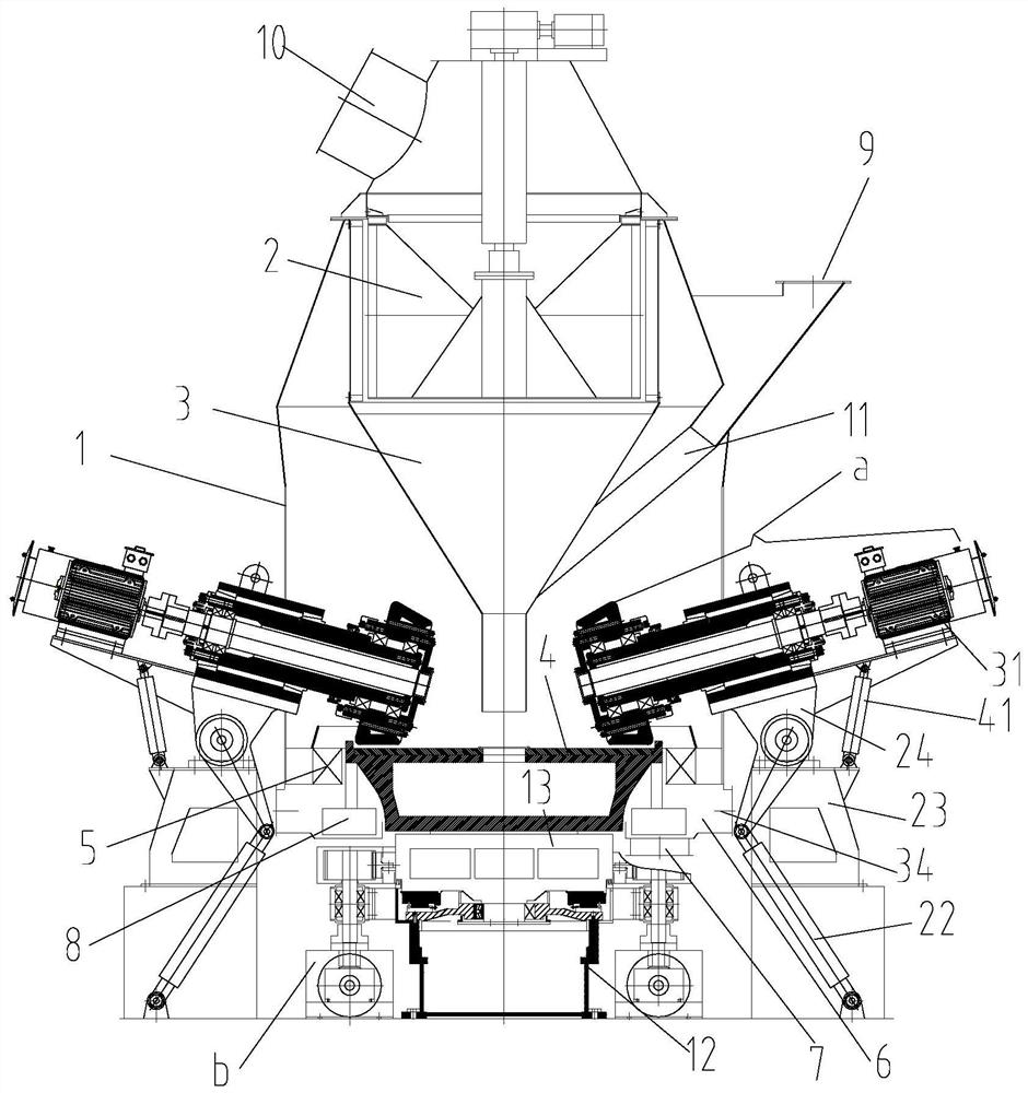
[0036] Such as Figure 1-5 This embodiment discloses a double-drive roller vertical mill, which includes a vertical mill cylinder 1, wherein the inner chamber of the vertical mill cylinder 1 is provided with a powder separator 2, an inner ash hopper 3 and a millstone 4 sequentially from top to bottom; Wherein a circle of spout ring 5 is arranged between the grinding table 4 a...


PUM


Abstract

The invention provides a double-driving roller type vertical mill, which comprises a vertical mill barrel body, wherein a powder selection machine, an inner ash hopper and an abrasive disk are arranged in sequence from top to bottom in the inner cavity of the vertical mill barrel body; the bottom of the abrasive disk is installed and fixed on the output supporting connection disk of a weight carrying supporting barrel body; one end of each transmission grinding roller mechanism is positioned in the vertical mill barrel body and is evenly distributed above the circumference of the abrasive disk; the outer surface of the output supporting connection disk is provided with a connecting flange; a connecting flange is locked and connected with a large tooth ring through a plurality of bolts; thelarge tooth ring drives the output supporting connection disk to rotate through a plurality of vertical heavy load speed reduction device; each transmission grinding roller mechanism comprises a loading hydraulic oil cylinder, a supporting seat, a rocker arm and a grinding roller component; and the vertical mill barrel body is provided with an annular air duct hole which communicates with a material discharging annular channel. By use of the double-driving roller type vertical mill disclosed by the invention, materials enter a powder grinding gap in a uniform way, powder grinding efficiency is improved, and operation stability is high.

Description

technical field [0001] The invention relates to the field of roller vertical mill equipment, in particular to a double-drive roller vertical mill. Background technique [0002] The roller vertical mills in the current technology are all driven by the transmission system to drive the grinding disc, and the fed materials fall into the center of the grinding disc, and are crushed by multiple groups of grinding rollers during the process of rotating with the grinding disc and performing centrifugal motion, and are passed through the friction force of the crushed material. Drive each group of grinding rollers to rotate. Due to the rotation of the grinding table and the passive rotation of the grinding roller, the material on the material layer will not be pulled into the rolling area well, but will form a piled extrusion state, the material bed will be unstable and the rolling efficiency will decrease. In addition, because the reducer of the roller vertical mill needs to transmi...

Claims


Application Information

Patent Timeline
IPC IPC(8): B02C15/00B02C23/30B02C23/32
CPCB02C15/007B02C23/30B02C23/32B02C2015/002B02C2015/008
Inventor 张桂才刘子河周勇武郭文哲
Owner 南京钜力粉体工程科技研究所有限公司
Why Eureka
Try Eureka