Coal drying device for coal-fired power plant

A coal-fired power plant and drying device technology, applied in the direction of drying gas arrangement, dryer combination, drying chamber/container, etc., can solve problems such as low energy utilization rate, secondary moisture of coal, heat energy loss, etc., and improve energy conversion efficiency and drying effect, prevent secondary moisture, improve the effect of dispersion

Active Publication Date: 2022-04-19
HUAINAN TIANJIAAN POWER GENERATION PLANT ANHUI ELECTRIC POWER CO LTD
View PDF0 Cites 0 Cited by
  • Summary
  • Abstract
  • Description
  • Claims
  • Application Information

AI Technical Summary

Problems solved by technology

[0003] At present, there are a large number of coal drying devices, mainly including rotary drum dryers, vertical tube airflow dryers and fluidized bed dryers, all of which require a large amount of hot air to be input. The thermal efficiency accelerates the evaporation of water to achieve drying, but in actual use, due to the simple structure and single function of traditional equipment, the hot air drying is released after contacting the coal, and a large amount of heat energy remaining in the hot air is lost, and the energy utilization rate is low. After the hot air is dried, it is transported to the storage mechanism or transported by the open-air conveyor belt. During the cooling process, a large amount of water vapor in the air condenses and easily leads to the secondary moisture of the coal, which has certain defects.

Method used


Image

  • Coal drying device for coal-fired power plant
  • Coal drying device for coal-fired power plant
  • Coal drying device for coal-fired power plant

Examples


Embodiment Construction

[0038] In order to make the technical problems, technical solutions and advantages to be solved by the present invention clearer, the following will describe in detail with reference to the drawings and specific embodiments.

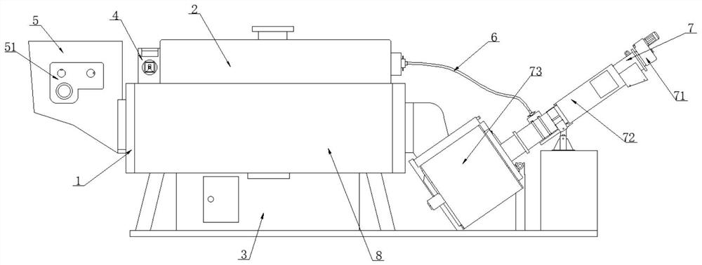
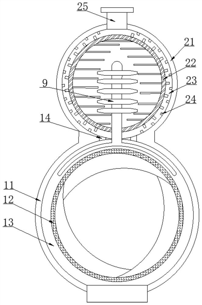
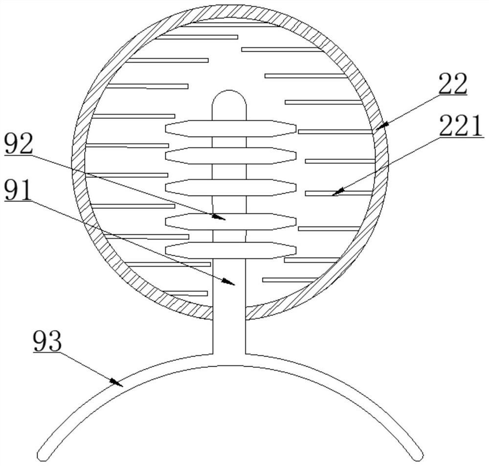
[0039] as attached Figure 1-7 The shown coal drying device for a coal-fired power plant includes a rotary drum dryer 1 and a hot blast stove 3, the output end of the hot blast stove 3 is connected to the bottom end of the rotary drum dryer 1, and one end of the rotary drum dryer 1 is fixed A crushing and filling hopper 5 is installed, and the interior of the crushing and filling hopper 5 is provided with an engaging crushing mechanism 51. The other end of the drum dryer 1 is fixedly connected with a heat preservation and conveying mechanism 7, and the top surface of the drum dryer 1 is fixedly installed with a waste heat recovery cylinder. 2. One end of the waste heat recovery cylinder 2 is fixedly installed with a dry air intake mechanism 4, and the ot...


PUM


Abstract

The invention discloses a coal drying device for a coal-fired power plant, specifically relating to the field of coal drying, comprising a rotary drum dryer and a hot blast stove, one end of the rotary drum dryer is fixedly installed with a crushing filler hopper, and the inside of the crushing filler hopper is provided with a meshing The crushing mechanism, the other end of the drum dryer is fixedly connected with the heat preservation conveying mechanism, the top surface of the drum dryer is fixedly installed with a waste heat recovery drum, one end of the waste heat recovery drum is fixedly installed with a drying air intake mechanism, and the other end of the waste heat recovery drum An air guide pipe is fixedly connected, and a heat exchange tube mechanism is fixedly installed inside the rotary drum dryer and the waste heat recovery cylinder. In the present invention, by setting the waste heat recovery cylinder structure, the heat exchange tube mechanism is used to exchange the heat energy of the hot air inside the drum dryer to heat the fresh air, and through the internal heat conduction cylinder structure, the residual heat of the dried hot air is conducted to heat the fresh air, so as to realize waste heat recovery. , improve energy utilization, and achieve the purpose of environmental protection and emission reduction.

Description

technical field [0001] The invention relates to the technical field of coal drying, in particular to a coal drying device for a coal-fired power plant. Background technique [0002] At present, my country's thermal power plants mainly use coal as the combustion fuel, and now the price of high-moisture coal is relatively low. More and more power plants are beginning to blend high-moisture coal. When high-moisture coal is burned in the boiler, it will vaporize and absorb a large amount of Heat absorption will bring a series of effects to the operation of the boiler unit at the same time, in order to solve the large amount of moisture contained in the coal. [0003] At present, there are a large number of coal drying devices, mainly including rotary drum dryers, vertical tube airflow dryers and fluidized bed dryers, all of which require a large amount of hot air to be input. The thermal efficiency accelerates the evaporation of water to achieve drying, but in actual use, due to...

Claims


Application Information

Patent Timeline
Patent Type & Authority Patents(China)
IPC IPC(8): F26B1/00F26B20/00F26B11/06F26B17/20F26B21/00F26B21/08F26B25/00F26B25/02F26B25/04F26B25/12F26B25/16B02C18/14
CPCF26B1/005F26B20/00F26B11/0486F26B17/20F26B21/001F26B21/002F26B21/004F26B25/04F26B21/083F26B25/002F26B25/02F26B25/12F26B25/16B02C18/142Y02P70/10
Inventor 李树伍刘彬杨泉王荣胜刘刚邵明义
Owner HUAINAN TIANJIAAN POWER GENERATION PLANT ANHUI ELECTRIC POWER CO LTD
Why Eureka
Try Eureka