Automatic ingot casting control system for vacuum electron beam furnace
A vacuum electron beam and control system technology, applied in the field of control systems, can solve problems such as limited heat dissipation, waste of manpower, and influence on the work of ingot drawing motors, so as to reduce time and manpower waste, improve processing efficiency, and ensure personal safety. Effect
- Summary
- Abstract
- Description
- Claims
- Application Information
AI Technical Summary
Problems solved by technology
Method used
Image
Examples
Embodiment 1
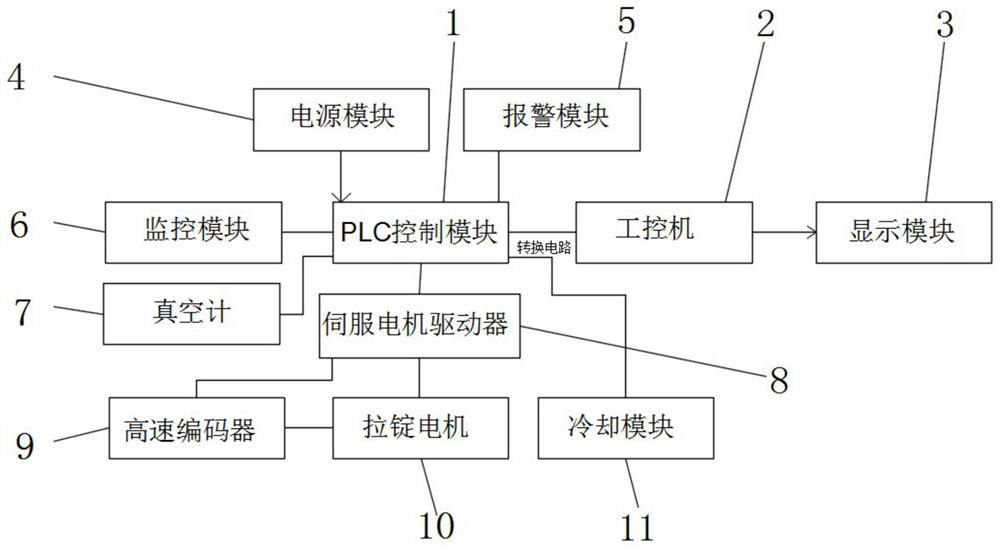
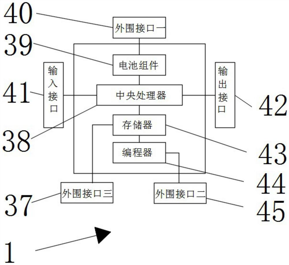
[0030] see Figure 1-7 According to an embodiment of the present invention, an automatic ingot casting control system for a vacuum electron beam furnace includes a PLC control module 1, an industrial computer 2, a display module 3, a power supply module 4, an alarm module 5, a monitoring module 6, a vacuum gauge 7, Servo motor driver 8, high-speed encoder 9, ingot drawing motor 10 and cooling module 11, described PLC control module 1 and described power supply module 4, alarm module 5, monitoring module 6, vacuum gauge 7, servo motor driver 8 and The cooling module 11 is electrically connected. It should be noted that the vacuum gauge 7 uses a microcomputer ionization vacuum gauge. The display module 3 includes a display screen that can display on-site monitoring images. The monitoring module 6 includes a camera that can monitor the on-site electronics. device, the alarm module 5 includes an alarm, which can give an alarm when an abnormality occurs, the PLC control module 1 is...
Embodiment 2
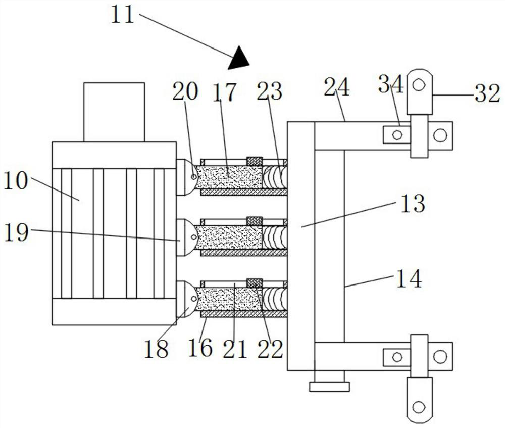
[0032] see Figure 4-7, the cooling module 11 includes a temperature sensor 12, a heat conduction plate 13, a water pipe 14, a water pump 15, a heat conduction sleeve 16, a heat conduction rod 17, a heat conduction block 18, a heat conduction block 2 19 and a movable shaft 20, and the drawing motor 10 The side wall is in contact with the heat conduction block two 19, and the two sides of the heat conduction block two 19 are fixedly connected with the heat conduction block one 18, and the heat conduction block one 18 is movably connected with the port of the heat conduction rod 17 through the movable shaft 20, so that the heat conduction block can be realized The rotation of the second 19, and the shape of the heat conduction block 18 is designed as a semicircle, and the four corners of the heat conduction block 19 are provided with chamfers, which can reduce the sharpness of the heat conduction block 18 and the heat conduction block 2 19, and the heat conduction rod 17 is close...
Embodiment 3
[0035] see Figure 4-7 , the mounting mechanism includes a mounting rod 24, a mounting hole 25, and a socket 26, the four corners of the heat conducting plate 13 are fixedly connected with mounting rods 24, and the end of the mounting rod 24 away from the heat conducting plate 13 has a socket 26. The function of the jack 26 is to facilitate the splicing and fixing with the extension rod when the length of the installation rod 24 is not enough. The two sides of the jack 26 are provided with a mounting hole 25, and the mounting hole 25 communicates with the jack for convenience. The insertion of the bolt, the surface of the installation rod 24 is provided with a movable mechanism, and the installation mechanism is convenient to connect the heat conduction plate 13 with the corresponding supporting parts, so that the heat conduction plate 13 can be supported and fixed;
[0036] Described movable mechanism comprises connecting block 28, rectangular hole 29, bearing 30, connecting ...
PUM
 Abstract
Description
Claims
Application Information
 - R&D
- Intellectual Property
- Life Sciences
- Materials
- Tech Scout
- Unparalleled Data Quality
- Higher Quality Content
- 60% Fewer Hallucinations
Browse by: Latest US Patents, China's latest patents, Technical Efficacy Thesaurus, Application Domain, Technology Topic, Popular Technical Reports.
© 2025 PatSnap. All rights reserved.Legal|Privacy policy|Modern Slavery Act Transparency Statement|Sitemap|About US| Contact US: help@patsnap.com


