
Micro-channel plate heat exchanger core with flow guide areas and fillets and manufacturing method of micro-channel plate heat exchanger core

A technology of micro-channel plate and diversion area, which is applied in the direction of indirect heat exchanger, heat exchanger type, lighting and heating equipment, etc., can solve the problem of restricting the promotion and development of Z-shaped micro-channel structure, Z-shaped micro-channel heat exchanger Efficiency reduction, fluid uneven distribution and other problems, to achieve the effect of suppressing thermal efficiency loss, reducing local resistance, good drainage and uniform distribution of fluid

Pending Publication Date: 2020-12-04
XIAN THERMAL POWER RES INST CO LTD
View PDF0 Cites 4 Cited by
  • Summary
  • Abstract
  • Description
  • Claims
  • Application Information

AI Technical Summary

Problems solved by technology

[0005] However, due to the large number of sharp bends along the flow direction, when the medium flows in the Z-shaped microchannel, flow separation occurs under the action of centrifugal force at the bend. Backflow occurs at the bend, which causes a large local resistance loss
In addition, due to the lack of a reasonable diversion area structure, a large number of microchannels, and an asymmetrical channel structure, the uneven distribution of fluid in the Z-shaped microchannel is more serious, which in turn reduces the efficiency of the Z-shaped microchannel heat exchanger. and an increase in resistance
[0006] In summary, although the Z-shaped microchannel has the advantages of strong heat transfer capability, the problems of large resistance loss and uneven fluid distribution are also significant, which restrict the further promotion and development of the Z-shaped microchannel structure.

Method used

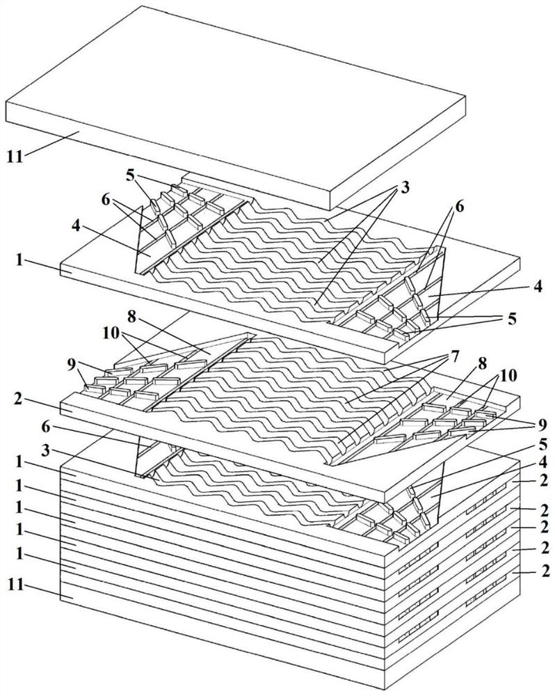
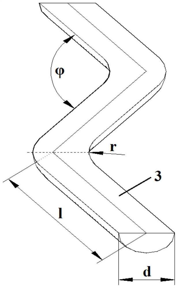
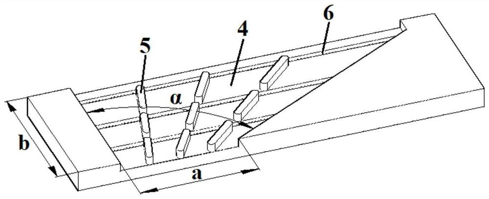

Image

  • Micro-channel plate heat exchanger core with flow guide areas and fillets and manufacturing method of micro-channel plate heat exchanger core
  • Micro-channel plate heat exchanger core with flow guide areas and fillets and manufacturing method of micro-channel plate heat exchanger core
  • Micro-channel plate heat exchanger core with flow guide areas and fillets and manufacturing method of micro-channel plate heat exchanger core

Examples


Embodiment

[0064] Cut the 3mm thick 316 stainless steel plate into 12 pieces of 280mm×150mm, cut the 10mm thick 316 stainless steel plate into 2 pieces of 280mm×150mm; use WP-760 cleaning agent to clean the surface of 14 metal plates; Using photolithographic anti-corrosion technology, the designed diversion area and flow channel structure were copied to the upper surfaces of 12 metal plates to form a specific anti-corrosion layer. The main component of the anti-corrosion layer was pentaerythritol triacrylate polymer; the 100 g FeCl 3 The crystal is dissolved in 300 ml of concentrated hydrochloric acid, and then diluted with 1200 ml of water to obtain the ferric chloride etchant. Put the 12 thin plates with the anti-corrosion layer on the conveyor belt of the etching machine, and use the acid-resistant pump to add the ferric chloride etchant. After 80 minutes at 55°C, the designed diversion area and flow channel structure can be etched on the upper surface of the plate; after checking tha...


PUM


Abstract

The invention discloses a micro-channel plate heat exchanger core with flow guide areas and fillets and a manufacturing method of the micro-channel plate heat exchanger core. The micro-channel plate heat exchanger core is formed by stacking and combining a plurality of high-temperature medium plates, a plurality of low-temperature medium plates and a plurality of end plates in the plate thicknessdirection; high-temperature medium runners and high-temperature medium flow guide areas are arranged on the upper surfaces of the high-temperature medium plates, and high-temperature medium flow guidefins and high-temperature medium collection grooves are arranged in the high-temperature medium flow guide areas; and low-temperature medium runners and low-temperature medium flow guide areas are arranged on the upper surfaces of the low-temperature medium plates, and low-temperature medium flow guide fins and low-temperature medium collection grooves are arranged in the low-temperature medium flow guide areas. The micro-channel plate heat exchanger core is high in heat transfer capacity, low in resistance loss, uniform in fluid distribution and high in heat efficiency.

Description

technical field [0001] The invention relates to the technical field of heat exchange devices, in particular to a core body of a microchannel plate heat exchanger with a diversion area and rounded corners and a manufacturing method thereof. Background technique [0002] Printed circuit heat exchanger (PCHE) belongs to the category of microchannel plate heat exchanger. PCHE has the advantages of compact structure, high temperature resistance, high pressure resistance, safety and reliability, etc. It is used in refrigeration and air conditioning, oil and gas, nuclear industry, chemical industry Widely used in industry, power industry and other fields. [0003] The heat exchange core is the core component of PCHE, which is welded by stacking and assembling metal plates. The main processing technology of the PCHE core includes (photo) chemical etching and diffusion welding: first, according to the designed micro-channel structure, a number of tiny (millimeter-scale) fluid channe...

Claims


Application Information

Patent Timeline
Patent Type & Authority Applications(China)
IPC IPC(8): F28D9/00F28F3/04F28F19/00B23P15/26
CPCB23P15/26F28D9/0037F28F3/046F28F19/00
Inventor 张磊高炜白文刚吴帅帅杨玉张纯张旭伟韩万龙吴家荣乔永强张一帆李红智姚明宇
Owner XIAN THERMAL POWER RES INST CO LTD
Learn More