
Drilling tool joint machine vision system and control method

A technology of drilling tool joints and control methods, which is applied in the direction of automatic drilling control systems, instruments, drill pipes, etc., can solve problems such as error-prone and low efficiency, and achieve the goal of reducing drilling costs, reducing manual operations, and reducing operating errors Effect

Active Publication Date: 2020-12-08
BEIJING JJC PETROLEUM EQUIP
View PDF4 Cites 0 Cited by
  • Summary
  • Abstract
  • Description
  • Claims
  • Application Information

AI Technical Summary

Problems solved by technology

[0005] In order to solve the problems of low efficiency and error-prone problems in the operation mode of manually aligning the drilling tool with the equipment in the prior art, the present invention provides a drilling tool joint machine vision system and control method

Method used


Image

  • Drilling tool joint machine vision system and control method
  • Drilling tool joint machine vision system and control method
  • Drilling tool joint machine vision system and control method

Examples


Embodiment Construction

[0041] In order to better explain the present invention and facilitate understanding, the present invention will be described in detail below through specific embodiments in conjunction with the accompanying drawings.

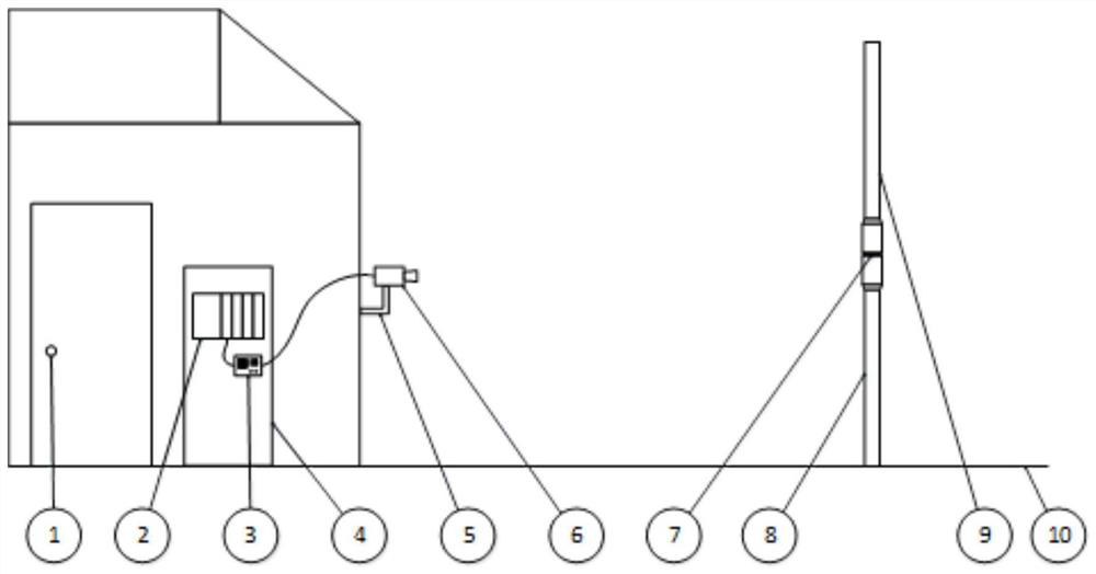
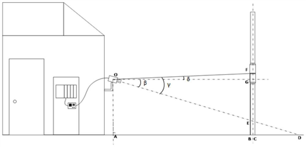
[0042] refer to Figure 1 to Figure 3 , the present embodiment provides a control method for drilling tool joint positioning, including the following steps:

[0043] S1: start the camera 6, take pictures of the drill joint 7, and record the image of the drill joint 7.

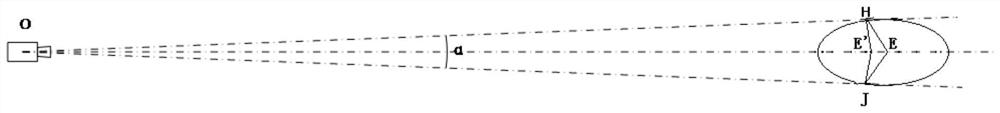
[0044] S2: The processor 3 electrically connected to the camera 6 is activated to receive the image of the drill joint 7 recorded by the camera 6 and obtain the visual angle α occupied by the drill joint 7 . According to the known horizontal distance L between the camera and the borehole axis 1 , the angle β between the camera and the horizontal plane, to obtain the radius and diameter information of the drilling tool.

[0045] S3: According to the radius information of the drill tool obtaine...


PUM


Abstract

The invention relates to a drilling tool joint positioning control method. The method comprises the following steps that S1, a camera is started to shoot an image of a drilling tool joint; S2, a processor receives the image of the drilling tool joint and obtains a visual included angle alpha occupied by the drilling tool joint, and radius information of a drilling tool is obtained according to a known horizontal distance between the camera and an axis of a drilling borehole and an included angle between the camera and a horizontal plane; and S3, according to the radius information of the drilling tool, a known height from the camera to a drill floor surface, an included angle between a connecting line of the drilling tool joint as well as the camera and an axis where the camera is located,and a horizontal distance from the camera to the drilling tool, height information from the drilling tool joint to the drill floor surface is obtained. The method has the beneficial effects that a position of the drilling tool joint is automatically recognized through machine vision, accurate position and diameter of the drilling tool joint can be transmitted to a control system in real time to allow control systems of various drilling tool operation devices to call the drilling tool joint, labor intensity and the probability of human errors are reduced, and operation continuity and efficiency are improved.

Description

technical field [0001] The invention belongs to the technical field of petroleum drilling machinery, and in particular relates to a drilling tool joint machine vision system and a control method. Background technique [0002] With the improvement of the automation level of oil drilling operations, automatic drilling tool operation equipment (such as top drive, iron driller, drill floor manipulator, etc.) is more and more widely used. On the drilling platform, drillers and drillers are mainly responsible for operating various drilling tool operating equipment. Through manual operation, the equipment is aligned with the drill tool joint to realize operations such as clamping, lifting, lowering, make-up, and breakout of the drilling tool. . When operating drilling tools, different hydraulic or electric drive power equipment such as winches, top drives, drill floor manipulators, iron drillers, etc. are required. When operating different equipment, it is necessary to re-align t...

Claims


Application Information

Patent Timeline
IPC IPC(8): E21B19/16E21B44/00G01B11/06G01B11/08
CPCE21B19/165E21B44/00G01B11/0608G01B11/08
Inventor 严峰刘忱李学军
Owner BEIJING JJC PETROLEUM EQUIP
Features
  • Generate Ideas
  • Intellectual Property
  • Life Sciences
  • Materials
  • Tech Scout
  • Unparalleled Data Quality
  • Higher Quality Content
  • 60% Fewer Hallucinations
Learn More